NICK WILLIAMS
DESIGN
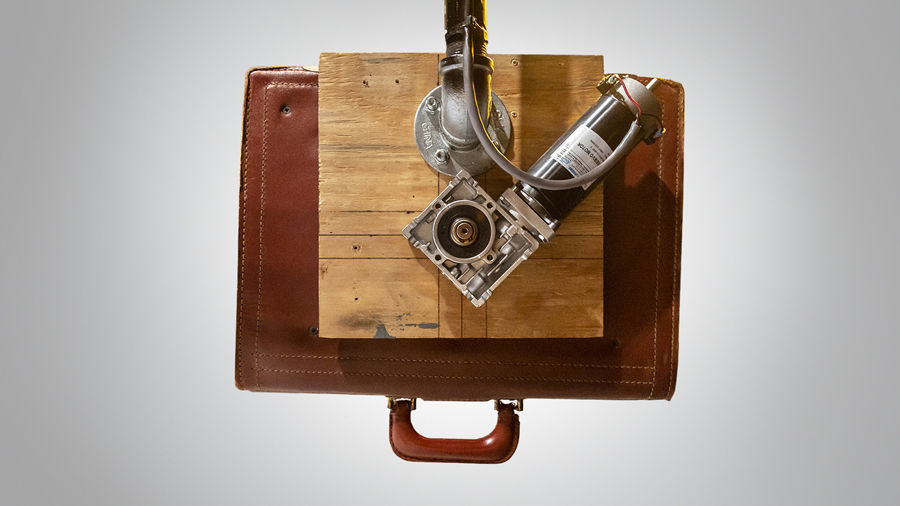
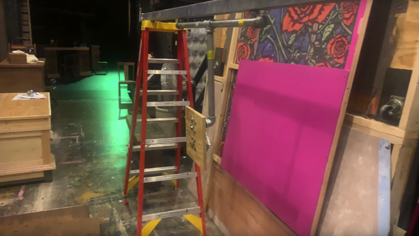
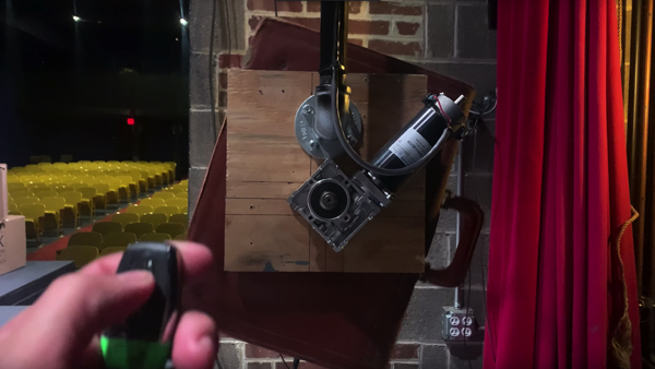
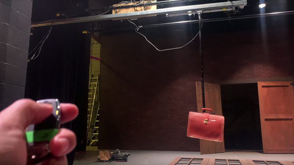
For a theatrical production of Bright Star, I was tasked with creating the illusion of a doctor’s bag rotating in slow motion in the sky. In addition to rotation, the bag needed to quickly move onstage in the dark, and then slowly move off stage, perfectly timed with the lighting cues. The project consisted of a barn door track, steel pipe, a servo motor, a stepper motor, limit switches, and a DMX enabled Arduino board.
This is a video of my first bag rotation test. On its own, the bag rotated too quickly for the Director’s preferences, so the compiled electronics included a simple PWM Speed controller. My wonderful colleague, Wendy, assisted in the making of this video.
Figuring out how to make the bag rotate was the easy part. Making the bag rotate AND move ten feet left to right on a community theatre budget? This was my challenge.
The theatre just happened to have an old 14’ barn door track hiding in the scene shop. I built a drop arm out of steel pipe and mounted it to the track hangars. This is a video of the first linear motion test.
The base servo motor rotated many times faster than the desire bag rotation speed. A worm gear speed reducer was added to the output of the servo to get the rotation close to our desired speed. The PWM speed control allowed me to dial it in perfectly.
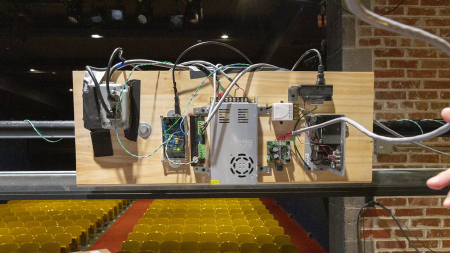
Prior to mounting the system on a static fly pipe twenty feet in the air, holding everything steady on a Genie lift, I mounted a mock up on one of the ETC motorized pipes. While the wiring isn’t the prettiest, this is the assortment of control electronics needed for the rig. From left to right: 110v AC Quad Box, Arduino Mega with DMX Shield, Stepper Motor Controller, Stepper Motor Power Supply, Wireless Relay Receiver, PWM Speed Controller, and Servo Motor Power Supply.
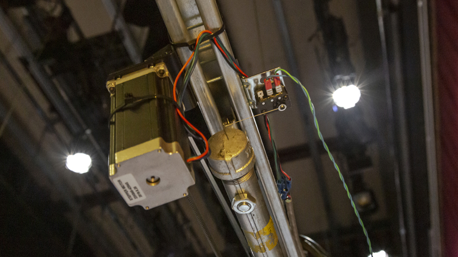
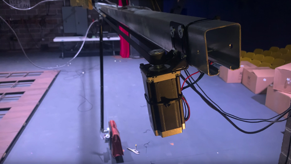
After the electronics were mounted and wired, the stepper motor was mounted to the barn door track. I chose to use a belt driven Nema23 stepper mechanism for the best combination of speed, torque, and precision. A Limit switch was also added for homing – each time the system was powered on, the stepper would bring the steel pipe toward the limit switch. Once the switch was triggered, the Arduino reset the step location to zero.
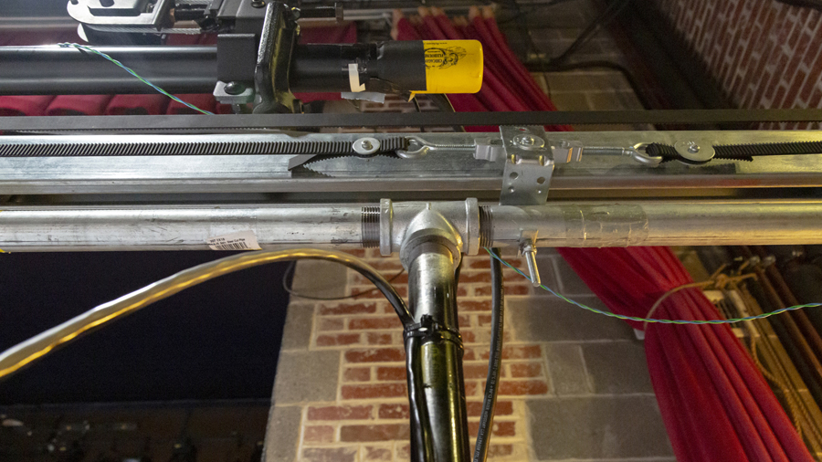
With the stepper in place, and the receiving pulley on the other end, it was time to mount the 15mm timing belt. In order to keep tension on the 28’ span of timing belt, a turnbuckle tensioner was used to connect the two ends of the belt. The opening of the turnbuckle was used to mount and L-bracket to the steel drop pipe.
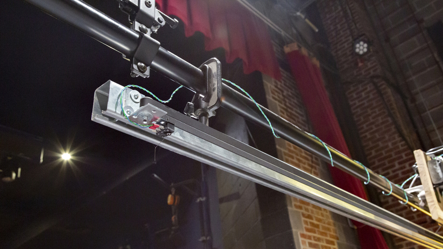
An additional limit switch was added to the other end of the rig. While I programmed ease-in and ease-out code into the motion of the drop pipe, this limit switch protected against runaway motor failures as the bag was moving on stage. Fortunately, this never needed to be utilized.
Now that the mechanics and electronics were completely installed, it was time to test out the speed of motion on stage and then off. And while it was calculated on paper, the test in the video is determining the precise number of steps from the homed zero to fully on stage. The end result turned out to be 12,000 steps!
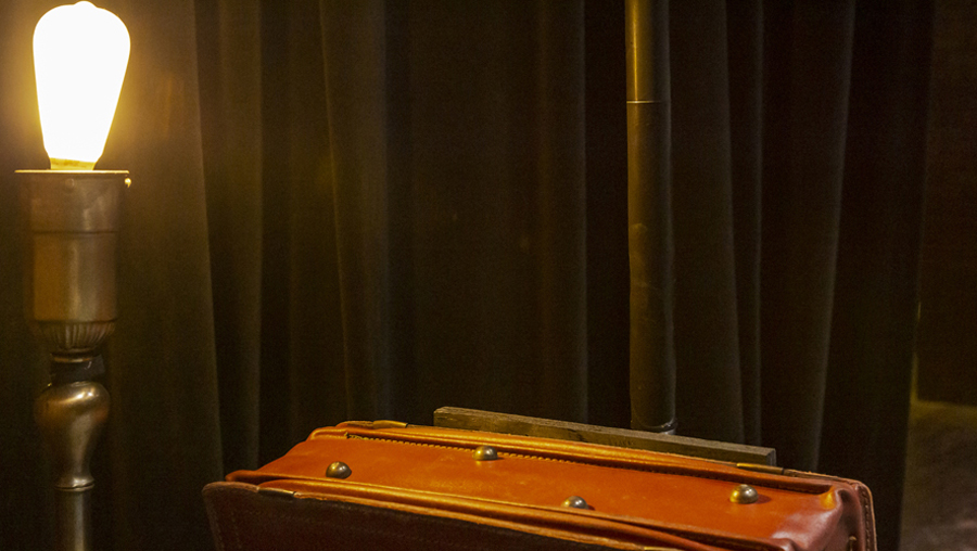
Now that the mechanics and electronics were working as desired, it was time to camouflage the steel drop pipe. I acquired a light absorbing adhesive foil that absorbs 99.9 percent of light. While seen in the photo directly next to the theatre’s ghost lamp, nothing but the bag could be seen by the audience.
This is a video of the final test before moving everything to the static fly pipe. I am using a handheld DMX generator to send 50% to channel 103, and the 49% when it’s time to move the bag back offstage. Working with the Lighting Designer, we were able to program an intelligent lighting fixture to move at precisely the same time and speed as the bag.
All of my other props reveal no plot points for shows. This video does. Only watch this video if you have already seen the show, or do not intend to see it. The video shows the end of Act One and the implementation of the rotating bag.
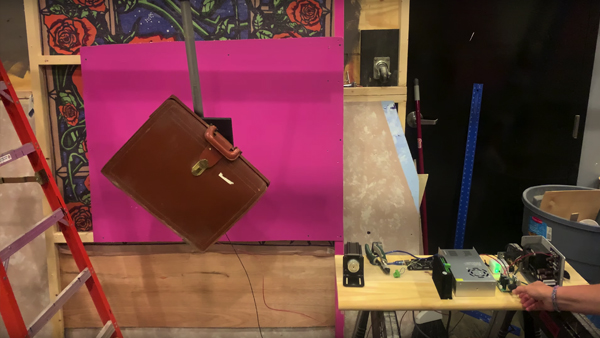
For a theatrical production of Bright Star, I was tasked with creating the illusion of a doctor’s bag rotating in slow motion in the sky. In addition to rotation, the bag needed to quickly move onstage in the dark, and then slowly move off stage, perfectly timed with the lighting cues. The project consisted of a barn door track, steel pipe, a servo motor, a stepper motor, limit switches, and a DMX enabled Arduino board.
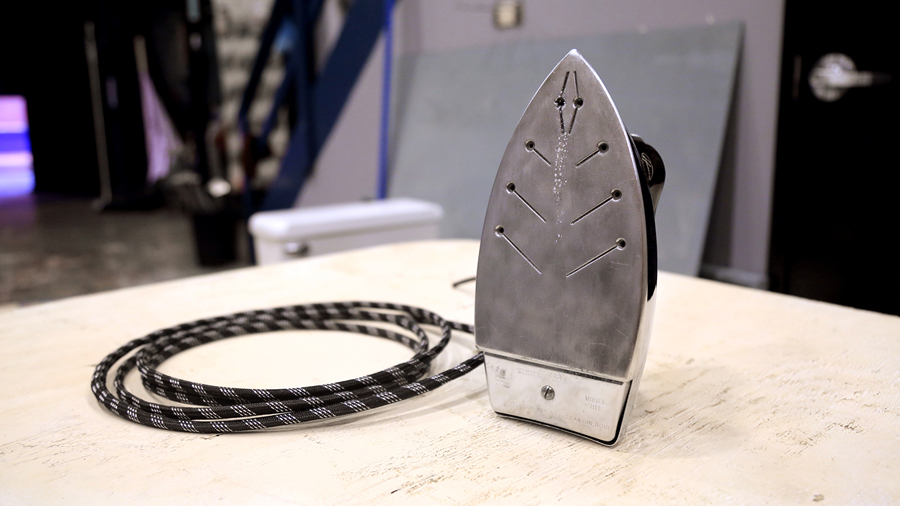
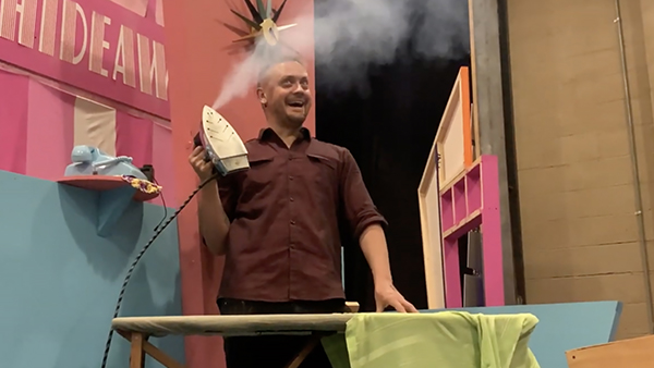
Shown here is an original 1950’s Model 011 Hoover steam iron. For a production of the musical Hairspray, the director wanted a particular scene to include an iron that shot bursts of steam as the cast members screamed in excitement. We originally ordered a mini-fogger used for small theatrical and magician smoke effects, but it didn’t provide sufficient force to shoot the steam far enough away from the iron.
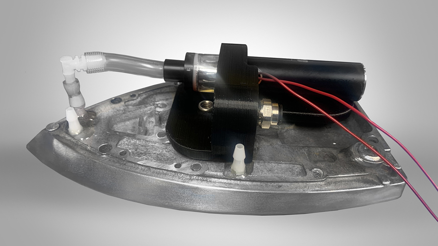
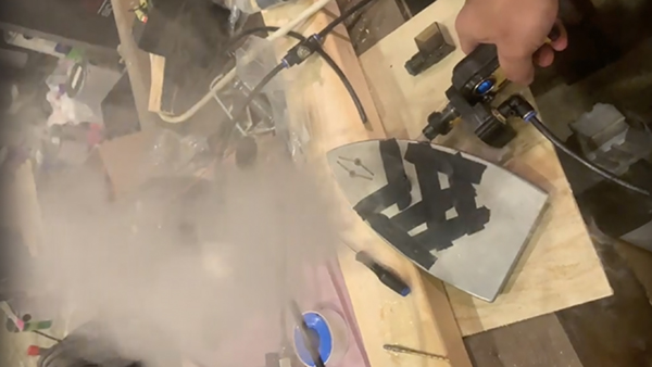
The iron’s internal water tank and heater element were removed to open up as much space as possible for the steam components. I dismantled the purchased mini-fogger to see how it worked and discovered it was simply a nicotine vaporizer (with flavorless, no nicotine juice) and a small fan, with a port assembly that guided the airflow from the fan into the air vents of the vaporizer. I designed and 3D printed a mount for a more powerful vaporizer, which incorporated an air cavity between the vaporizer’s air intake vents and an air tube connection. The trigger/power switch was also removed, and wires were soldered in its place that ran to the original steam switch on the iron.
To get the needed air pressure behind the steam for the bit to work, I mounted a two-gallon compressed air tank and 12v solenoid valve under the set piece, and I ran the solenoid trigger wires and air tube through sheathing that looked like the iron’s original power cord. The original steam switch on the iron controlled both the vaporizer and the solenoid valve, and the steam was routed through one of the original steam ports on the iron’s base.
This video shows my first working prototype. I tested different configurations of steam ports, but I couldn’t achieve the desired steam distance with any more than one port hole open.
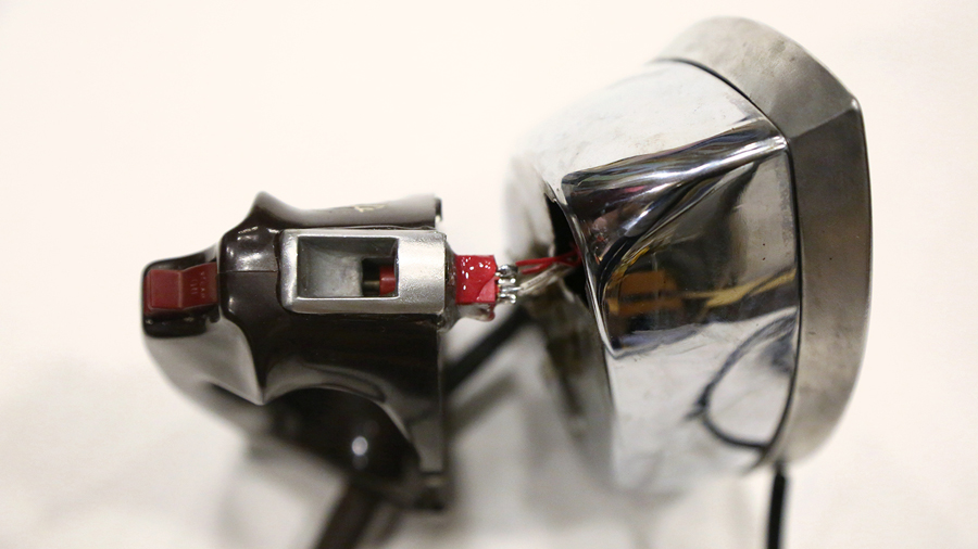
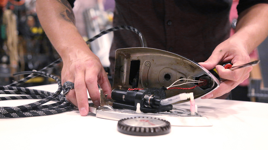
The original steam switch mechanism included a steel rod with a plunger on the end that, when pressed, allowed water from the internal tank to pass into the heated channels in the base of the iron. The rod was cut to a length that fit in a drilled-out cap of a DPDT switch. Activating the iron’s steam switch pressed down on the DPDT switch, which triggered the solenoid valve to open the air tank and the vaporizer to generate smoke.
Turn your volume down for this video! I may or may not have been a little too excited that the final design worked as desired. This was my first test of the installed prop.
This is a short clip of the scene in Hairspray where the steam iron was used.
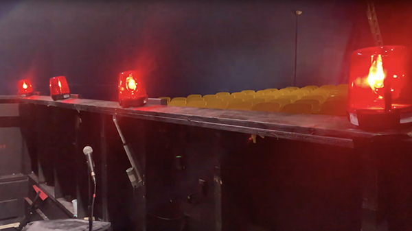
Not as difficult, but equally as fun to rig up, this is a video of the police lights that appear at the end of Act One when the cops show up to arrest everyone at the dance party. Hidden for most of the show, these lights are mounted on a board that moves with a remote-controlled linear actuator. Channels 1 & 2 of a wireless relay activate the lights, and channels 3 & 4 activate the up/down travel of the actuator. Instead of a Sound Effect, a 12v police siren was wired up back at the sound booth that coincided with the lights.
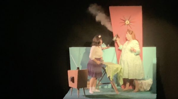
Shown here is an original 1950’s Model 011 Hoover steam iron. For a production of the musical Hairspray, the director wanted a particular scene to include an iron that shot bursts of steam as the cast members screamed in excitement. We originally ordered a mini-fogger used for small theatrical and magician smoke effects, but it didn’t provide sufficient force to shoot the steam far enough away from the iron.
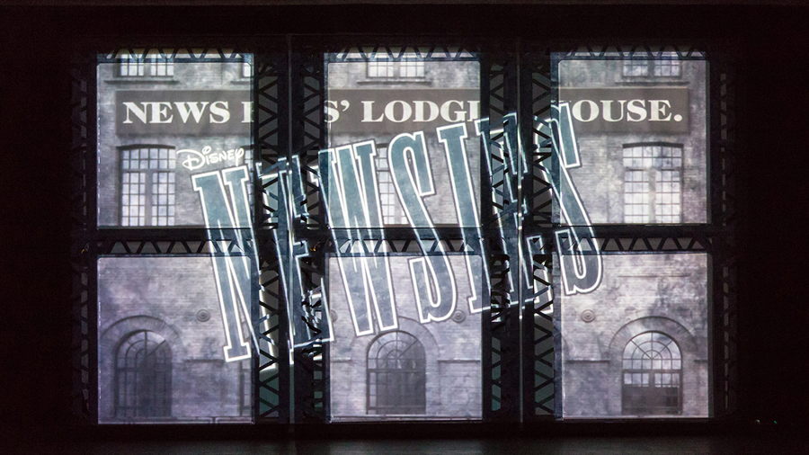
If you were to ask me about my proudest professional achievement, the wireless projection screen system I designed for Newsies would be it. The Broadway production had three, three-story towers that moved all over the stage. Projection screens moved in and out of the front face of each level of each tower. This wasn’t technology that could be bought off the shelf, and the motorized rollers that came close were way out of our small theatre’s budget.
So I built them from scratch.
I sourced projection fabric that could be backlit to see through when needed, servo motors with enough torque to lift the specified weight of the projection surfaces, batteries with capacities sufficient to run an entire weekend of shows, WiFi arduino boards, sensors, IR LEDs, and bearings (Oh My!), and I designed and 3D printed enclosures to hide all of this within the set pieces.
This is a video of the first time I had the system working properly. Each screen is independently and wirelessly controlled. They are connected to a master Arduino WiFi board at Front of House, but if any one screen lost connection with the master, the mesh network I created allowed that screen to seamlessly connect to its neighbor and continue receiving cues. A 6v dry cell battery powers the servo motor on the end of each 4” PVC drain tube that holds the projection fabric. Infrared sensors tell the arduino boards when the screen is fully up or down. Eye hooks on the ends of a dowel rod at the bottom of each screen traveled along tie line to keep the screens from waving out of place when the towers moved.
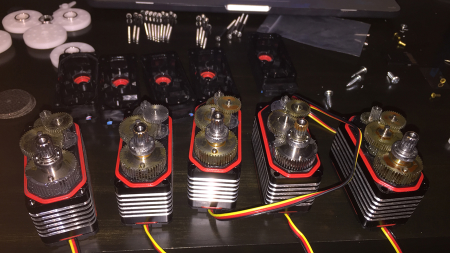
Most servo motors are limited to a specific range of motion - 180 degrees is common. Since I needed the roller mechanism to rotate 360 degrees multiple times, I had to modify all of the servos. These servos had both a mechanical and an electrical end stop. The mechanical stops were physical “nubs” on the side face of one of the internal gears that stopped the gear from rotating when it collided with the next gear. A Dremel was used to grind off this nub. Electrically, a potentiometer connected to the main drive shaft sensed precise position, stopping the servo once it reached its maximum range. The potentiometer was removed, and it was replaced with two identical resistors, which tricked the internal controller board into thinking the servo was always centered.
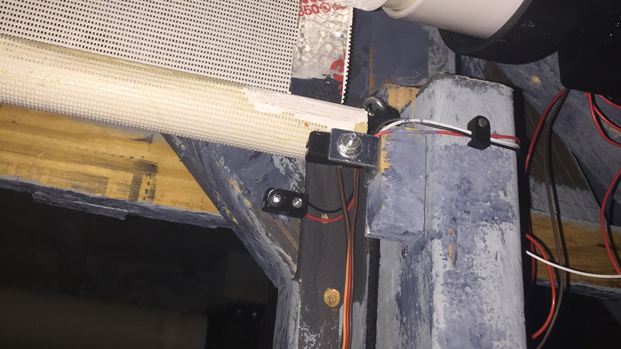
Shown here are the infrared LED break-beam sensors, located at the top of the set piece’s front opening. There is another pair at the bottom. Since the projection surface was semi-transparent, a strip of foil tape was added to the edge of the rear face to block the IR sensors when the screen was in their path. As the screen was moving up, when the top sensor saw the IR LED, it told the arduino board to stop moving the servo. Conversely, the bottom sensor would see the IR LED when the screen was moving down, and the point when it no longer saw the LED was the point the arduino knew to stop moving the servo.
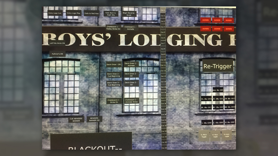
SI needed a piece of software that could trigger both the position of the screens and the images/video that were projected to them. I discovered a program called TouchDesigner, by Derivative. It’s the most capable software I have ever seen for this purpose, but figuring out how to use it was WAY over my head at the time. I spent a couple weeks reading the TouchDesigner forums, watching training videos, and corresponding with the fine folks over at Derivative to learn how to be just dangerous enough to pull off what I needed for this show.
I learned how to send Serial data out of the USB port into my Arduino master board. I learned python programming language, on which TouchDesigner is based, to set up cues that sent a binary 1 or 0 to the arduino to trigger the up or down position of each screen. I learned how to projection map the screens, so the video and images always landed within the projection surfaces.
This is a video of one of the first projection scenes in Newsies. All of my animations were first created in Adobe After Effects, and then triggered to play in TouchDesigner. From 0:47 to 1:07 is the first screen move, and then the big reveal is 1:45 to 2:05, if you would like to skip ahead.
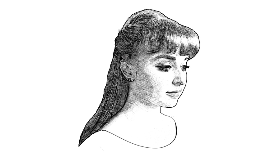
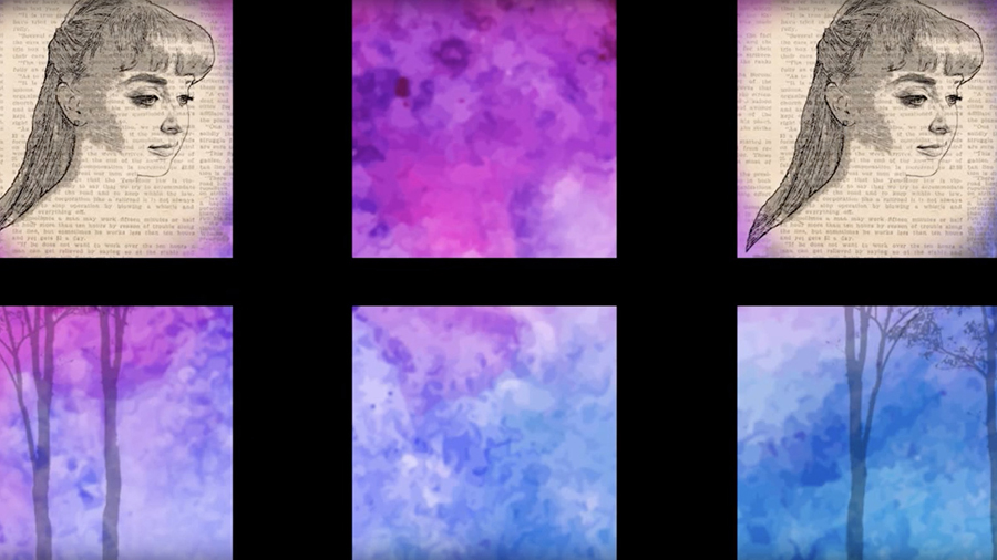
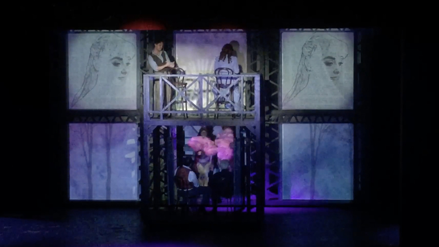
Later on in the show, Jack draws Katherine’s face on a newspaper with charcoal. The animation of this drawing is shown on one of the screen panels. I used an image of the cast member in our production to generate this animation.
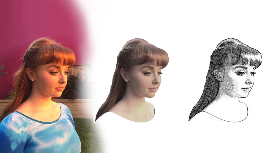
The left image is the original picture taken in our theatre’s courtyard. The middle image has been masked out from the original. The final image is the result of passing the middle image through an effects filter in an app on my phone.
Once I had the final image that resembled a charcoal sketch, I broke it up into many layers in Photoshop. The file was then sent to After Effects, and using hundreds of keyframes, the individual lines or shading were revealed in a particular order and pace to look as though they were being hand drawn. This is a video of the source animation used in the show.
This video shows the charcoal drawing animation in our production. The animation was shown on two screen panels to allow viewing from both sides of our audience.
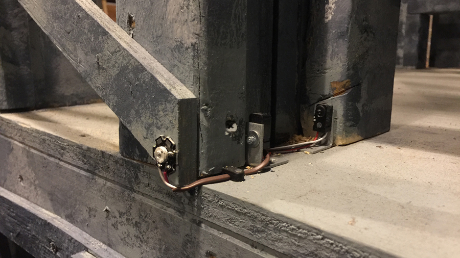
I wanted to incorporate IR tracking in this production - TouchDesigner’s ability to process it was the primary draw to utilize the software. Since the projection towers moved all around the stage, I wanted to be able to guarantee that the projections would always land precisely within the surface of the screens. Shown here on the front of the tower is a high power 3W Infrared LED. I mounted one on each corner of the projection screen area.
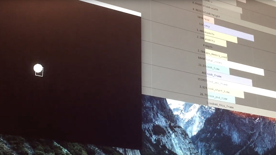
This is a video of my first test of TouchDesigner’s IR tracking feature. An IR LED is aimed at a modified CCTV camera (I figured out that the magnetic tape in an old floppy disk blocked visible light, but allowed infrared light to pass - a square of this tape was placed over the CCTV camera sensor). As the LED is moved around in the camera’s frame, the software senses the horizontal and vertical position of the white blob created by the LED. Using this data, I could map the corners of the screens, and modify the size and shape of each projection to land within the projection surfaces.
Unfortunately, technical issues with the mesh network code took more time than expected to resolve, and I was unable to incorporate this incredible feature.
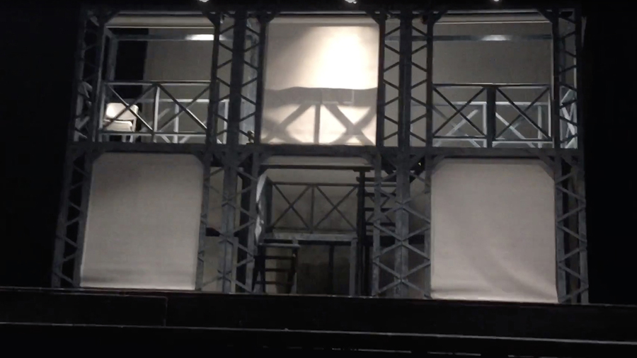
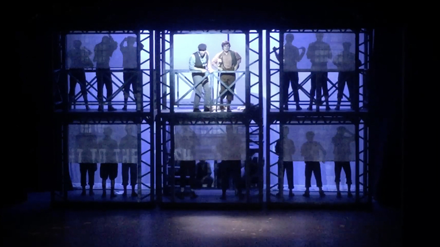
If you were to ask me about my proudest professional achievement, the wireless projection screen system I designed for Newsies would be it. The Broadway production had three, three-story towers that moved all over the stage. Projection screens moved in and out of the front face of each level of each tower. This wasn’t technology that could be bought off the shelf, and the motorized rollers that came close were way out of our small theatre’s budget.
So I built them from scratch.
I sourced projection fabric that could be backlit to see through when needed, servo motors with enough torque to lift the specified weight of the projection surfaces, batteries with capacities sufficient to run an entire weekend of shows, WiFi arduino boards, sensors, IR LEDs, and bearings (Oh My!), and I designed and 3D printed enclosures to hide all of this within the set pieces.
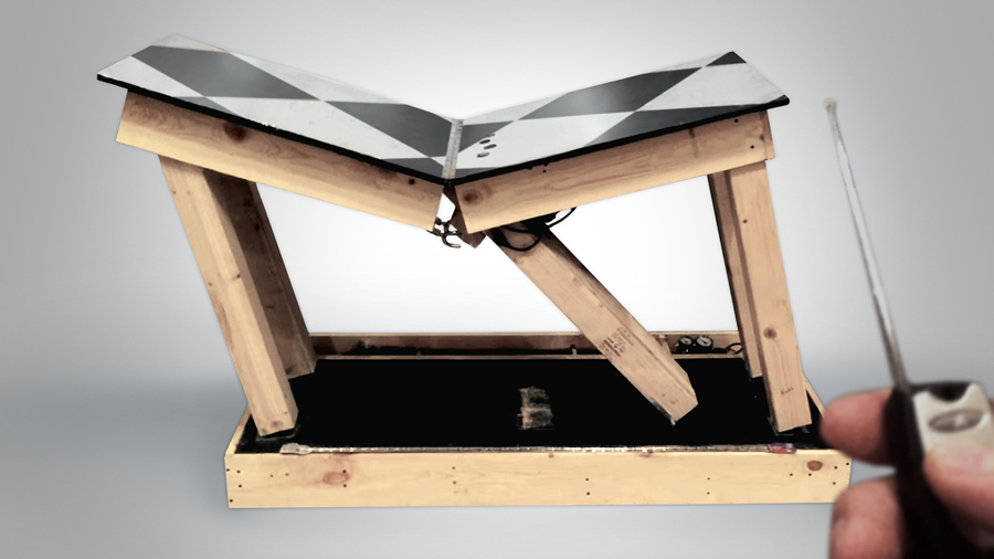
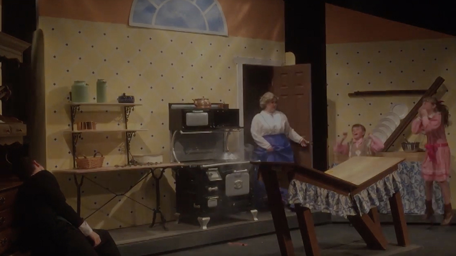
Prior to our production of Newsies, the props I designed for Mary Poppins were my proudest achievement. I knew nothing about pneumatics before this show, but I spent the time researching all about it in order to build this table. There’s a scene in the show where the family butler accidentally destroys the kitchen while baking a cake, and Mary Poppins arrives to restore the damage done.
This is a video of the first time the table was working as designed. In the Broadway production, the table was part of a larger set piece that moved on and off stage. This allowed an “umbilical cord” of sufficient power to control the mechanics in the table. Since we had to roll just the table by itself on and off stage, I designed a wireless, battery-powered, pneumatic system built into the base of the table.
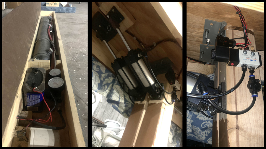
The left picture shows the control system that is mounted under a flap in the base of the table. It consists of a two-gallon compressed air tank, a 12v battery, a wireless relay, and a pressure gauge to monitor the air in the tank. Not shown is an LED display that monitors the voltage level of the 12v battery.
The middle picture shows the two pneumatic cylinders mounted to the center posts of the table. The table’s outer legs were mounted to the base with door hinges to allow bending in place, while skate bearings were mounted at the base of the center posts to allow them to roll to the side. Tension springs were attached to the opposite side of the center posts to assist in bringing the table back up to normal position. The right image shows one of two solenoid valves that controlled the direction of air into the pneumatic cylinders.
Here is a video of the entire kitchen scene, both being destroyed by the butler and repaired by Mary Poppins. I also built the rig with the plates that roll into the sink, rigged the oven door to close on its own, and modified the hutch on the left with falling plates. The top row plates are mounted to small skates that travel up and down a track - the shelf is held up by a doorknob that is turned to drop the shelf. The bottom drawer has two pairs of very high strength ball bearing sliders - strong enough to hold the weight of the butler.
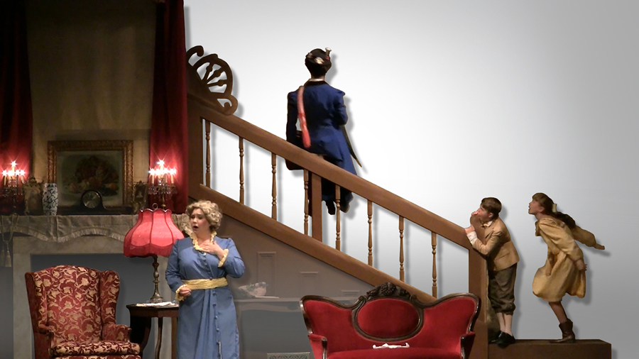
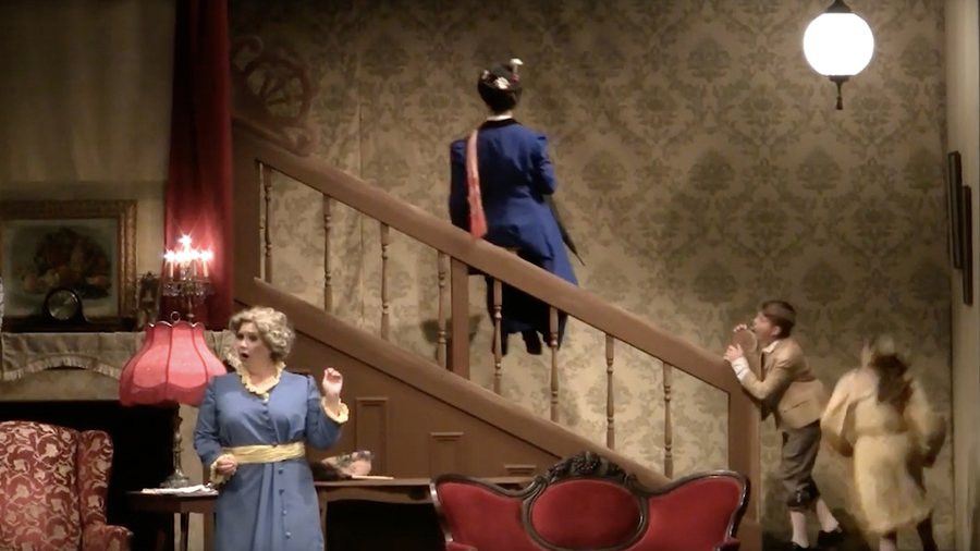
It is easy to slide down a banister. It’s not quite so easy to make someone slide up one. I looked into many automatic, motorized options to pull this off, but they were all too expensive for our budget. Instead, I incorporated a compound pully system, with a carriage connected to aircraft cable that collected onto a large wheel under the set.
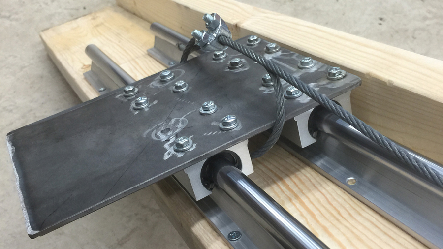
Two 12ft linear rails were mounted to the banister, with four ball bearing pillow blocks mounted to a steel plate.
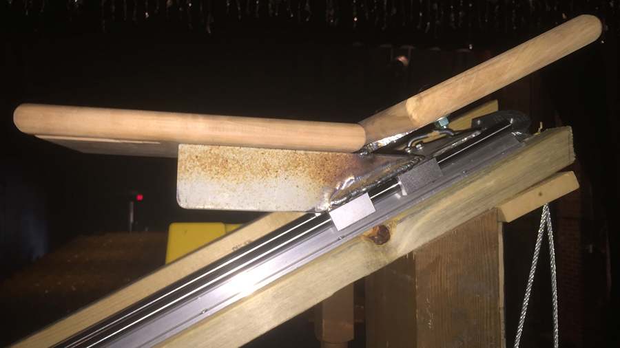
A seat was fabricated and welded to the rolling steel plate.
This is a video of the banister trick during the show.
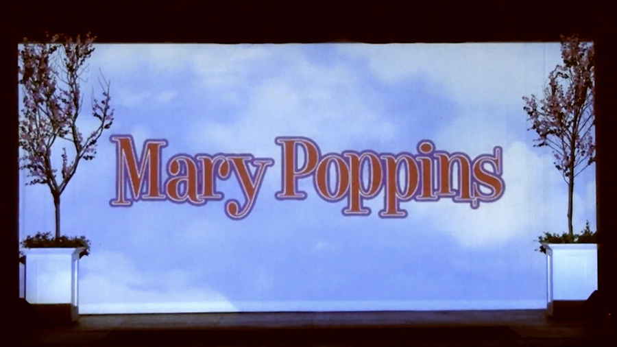
The video above shows animation of the walk-in projection at the start of the show. The audience sees the Mary Poppins logo for the 30 minutes prior to curtain, and this logo begins to animate over time, first with slowly moving clouds, then faster clouds, then the letters blowing away. I broke up the Illustrator file created by our director into one layer per letter, and then animated each to fly away with the musical score. Since I also run sound for all of our shows, the music you hear is the multi-tracked mix I created for the archive DVD of our production.
Skip to 0:40, 2:10, 2:40, and 4:00 if you prefer not to watch the entire 5:50 video.
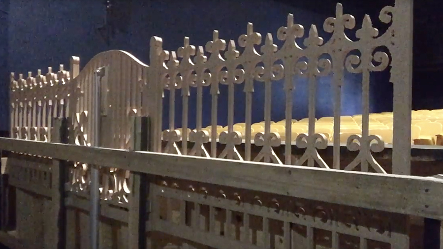
When Mary Poppins first arrives to the Banks home in the movie, she flies toward the fence surround the property, and then hops over it. This is the fence I mounted to a 30” linear actuator that rose from the orchestra pit during this scene. The rigging crew performed this same motion, making our Mary poppins appear to hop over this fence.
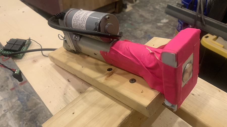
For comedic relief, our director wanted Miss Andrew’s bag to fall from the sky as Mary Poppins pushed her out of the home. In order to pull this off, I mounted a short throw linear actuator, connected to a wireless relay, to a pipe directly above and behind the proscenium. To force the handles of the bag off the post of the actuator, this foam plate was installed flush with the end of the actuator when it was fully retracted. A remote control from the sound booth triggered the actuator.
Here is a video of Miss Andrew’s bag falling from the sky during our production.
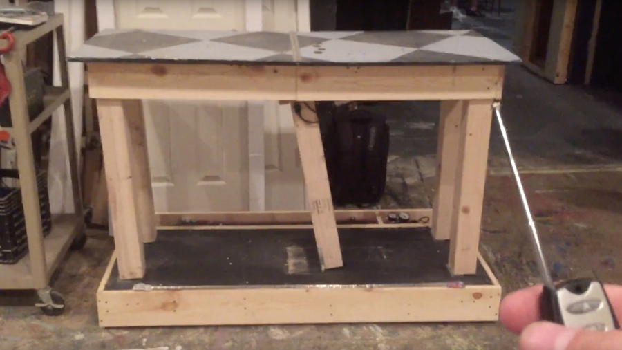
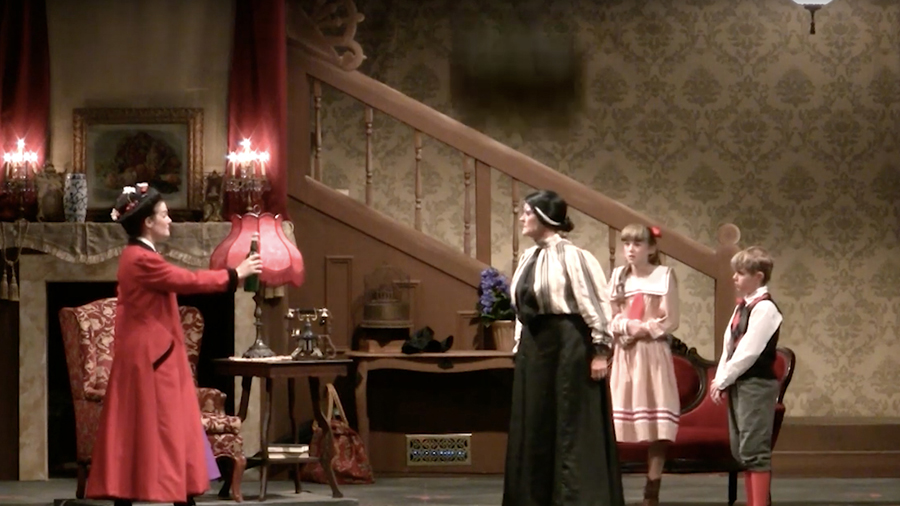
Prior to our production of Newsies, the props I designed for Mary Poppins were my proudest achievement. I knew nothing about pneumatics before this show, but I spent the time researching all about it in order to build this table. There’s a scene in the show where the family butler accidentally destroys the kitchen while baking a cake, and Mary Poppins arrives to restore the damage done.
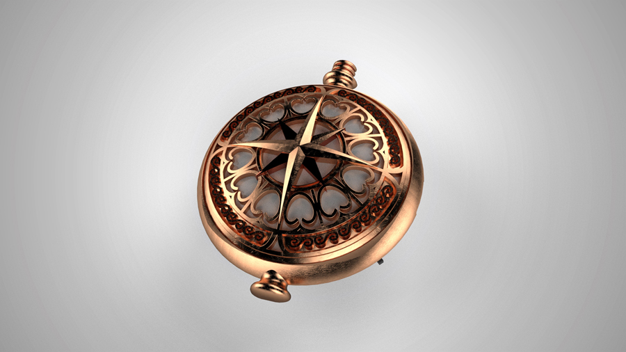
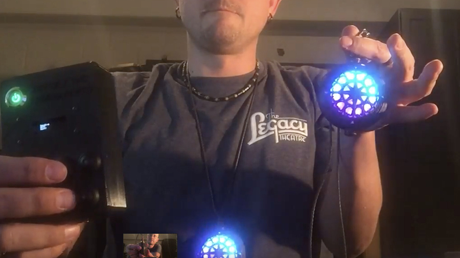
Shown here is a CAD model of a special effect amulet I designed for a production of Peter and the Starcatcher. I had not yet used Solidworks prior to this show, but the company for which I had just started working needed a Solidworks designer. I spent a week absorbing hours of training videos, and this is the first design I developed in the software.
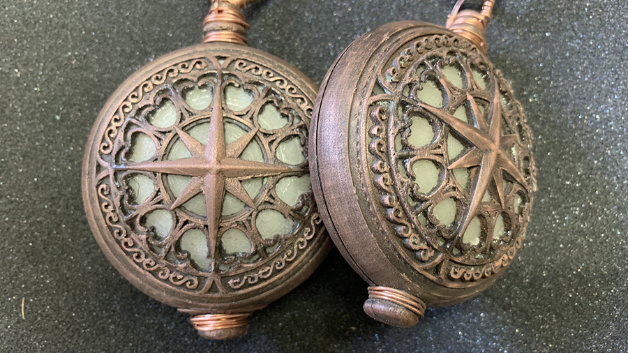
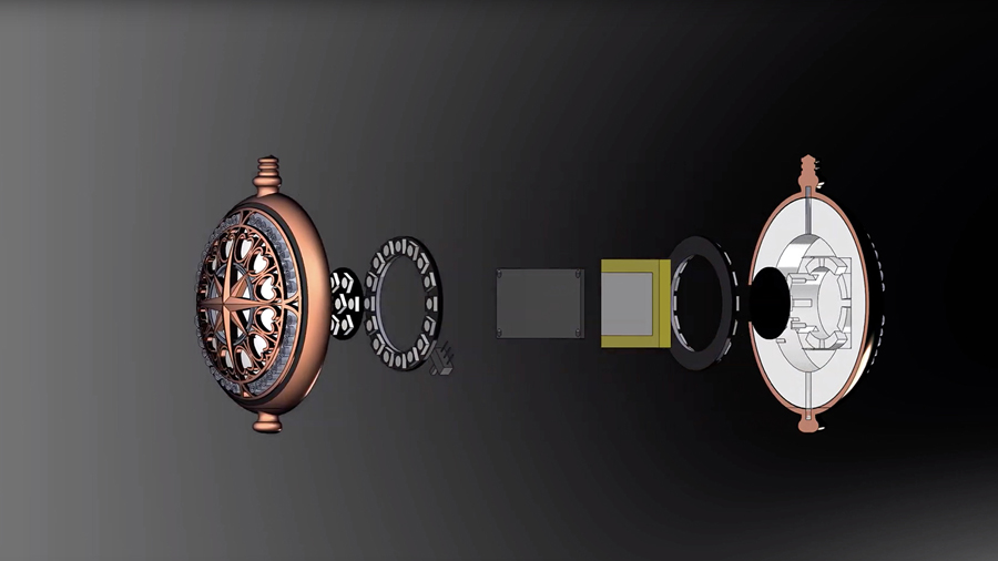
In the production, Molly and her father, Lord Aster, communicate with each other from two ships through these amulets. Internally, each amulet contains a Lithium Ion Polymer battery, an Adafruit Feather 32u4 Radio with RFM69HCW Module, two 12-pixel Adafruit RGBW NeoPixel rings, and a pair of 7-pixel RGBW Adafruit NeoPixel Jewels. Once all of the components were measured and created as parts in Solidworks, I laid them out as desired and built the white shell around them, which was 3D printed with a translucent white filament. The external shell was printed with a copper-infused filament that allowed the final 3D print to be painted, sanded, and polished to look like aged, oxidized copper.
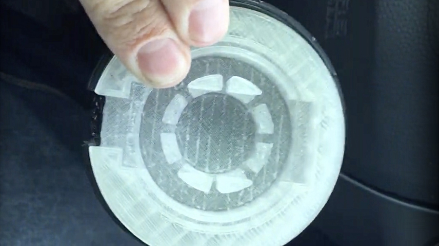
Shown here is the first prototype printed on the 3D printer. You can see all the cavities and wire paths created to hold all the internal components packed tightly together.
This video is a quick exploded view animation showing the layout of the internal components.
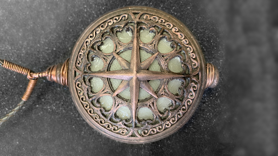
Each external shell was first hit with a very thin layer of black spray paint, and quickly wiped off before drying. This filled all the deeper cracks with paint. The surface then received a combination of steel wool and a wire brush to reveal the tiny copper particles in the filament. Lastly, a thin layer of Brasso Metal Polish was applied and rubbed in with a cloth. The areas that the cloth could not reach became oxidized by the polish.
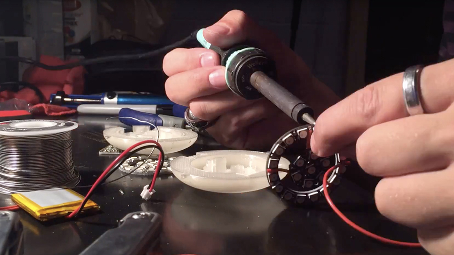
This video is a timelapse of one of the amulets being assembled.
In this video, I show the four light sequences I programmed onto the arduino boards.
Since the props in our productions generally get rented out to other theatres across the country, I created this instructional video to go over the proper operation and maintenance of the amulets and their remote control. This is the video that is sent along with each rental.
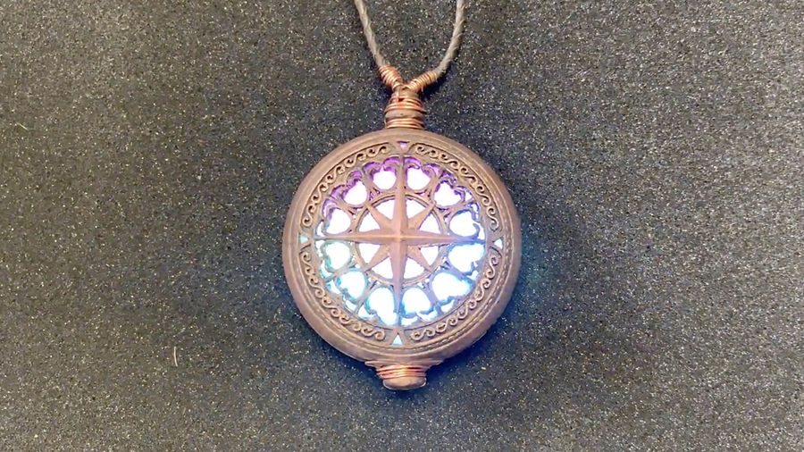
Shown here is a CAD model of a special effect amulet I designed for a production of Peter and the Starcatcher. I had not yet used Solidworks prior to this show, but the company for which I had just started working needed a Solidworks designer. I spent a week absorbing hours of training videos, and this is the first design I developed in the software.
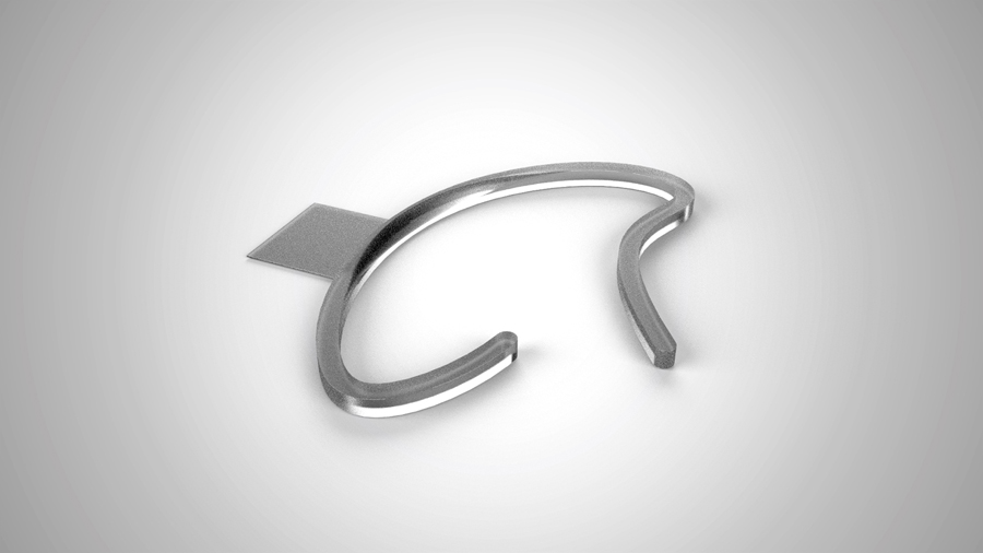
Up until my production of Newsies, I had generally run all of the cast microphones through hair or a wig, attaching them with elastic-wrapped wig clips. Since Newsies had so many hats on the male characters, I needed to place them over the ear. We only owned Countryman B3s, however, and the well known metal ear clips and tools to attach the mics were too expensive at the time. I designed this plastic ear clip in Solidworks and printed a few dozen of different sizes to fit everyone in our cast.
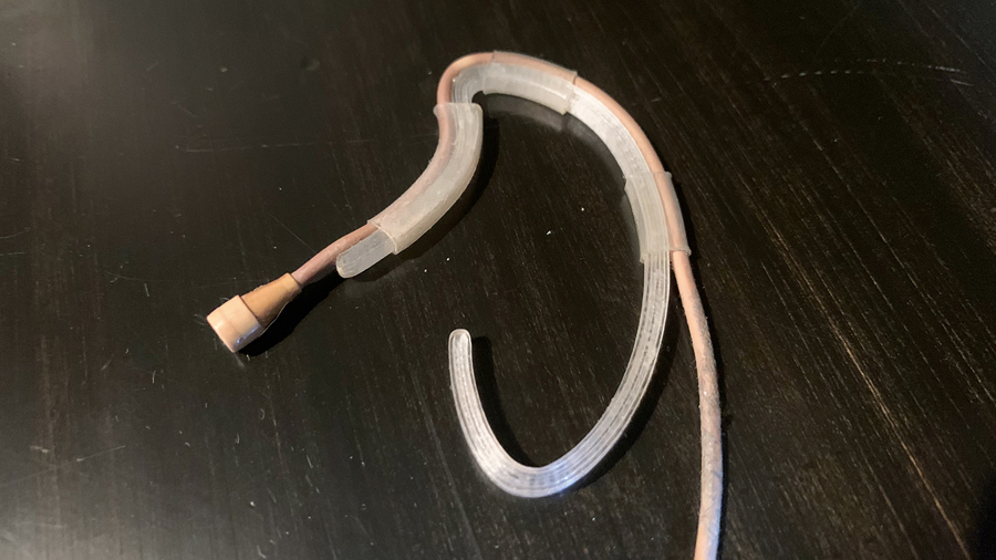
The Countryman B3 was ran above and behind the 3D printed clip. Clear heat shrink tubing was applied in three areas, binding the mic cable to the contour of the clip. The square tab on the back side of the clip was added as a reinforcement area for surgical tape to be applied on the cast member.
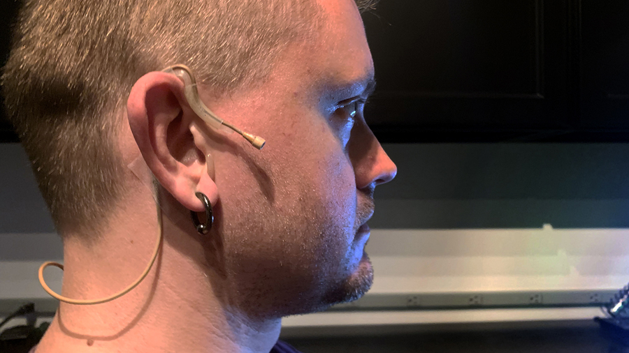
The shape I developed fits snugly around the ear, even without tape. After a short while, it’s easy to forget the mic is even there!
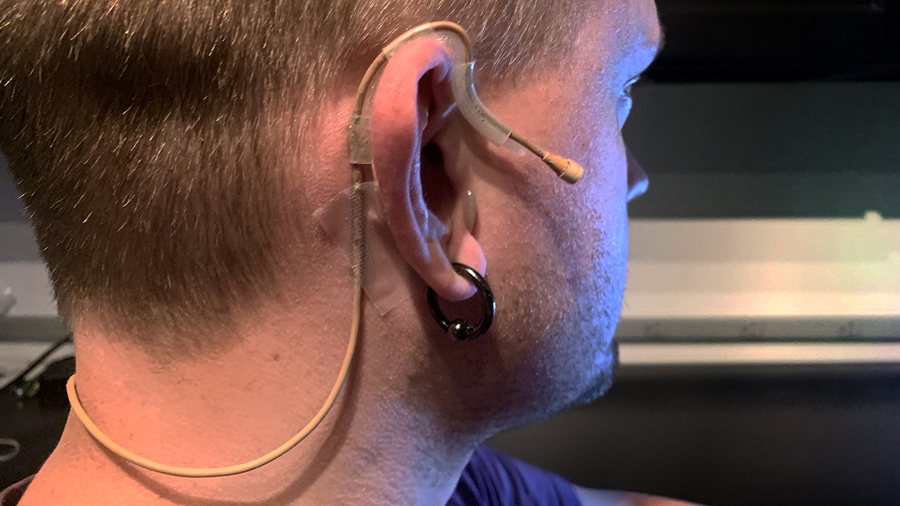
The mic cable is taped right behind the ear, coiled slightly to stay tucked against the head, and then taped again at the center of the neck.
Up until my production of Newsies, I had generally run all of the cast microphones through hair or a wig, attaching them with elastic-wrapped wig clips. Since Newsies had so many hats on the male characters, I needed to place them over the ear. We only owned Countryman B3s, however, and the well known metal ear clips and tools to attach the mics were too expensive at the time. I designed this plastic ear clip in Solidworks and printed a few dozen of different sizes to fit everyone in our cast.
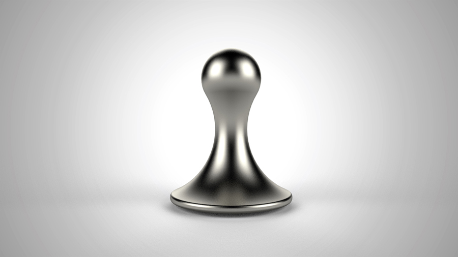
Imagine Magnets is a brand I developed in 2018 for the purpose of selling on e-commerce sites, starting with Amazon.com. Most refrigerator magnets on Amazon were bulky, ugly, or not strong enough to hold anything up. I wanted to create something elegant that was strong enough to be used for more than just holding up a single picture.
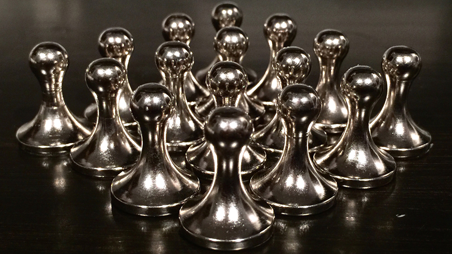
I created a few different models in Solidworks, and this was the first to be manufactured. After creating a manufacturing drawing, I reached out to factories in China to machine and nickel-plate the steel shell, install the magnet, and produce the packaging based on my Adobe Illustrator design. I placed an initial order of 400 packages of 16 magnets to test the market and see how well they would sell.
Unfortunately, the day my order arrived, Amazon removed my listing. Though there are dozens of other very similar products, Amazon does not allow small neodymium magnets, as children may think they are candy and swallow them. My listing just happened to get flagged for review by their bots. Lesson Learned!
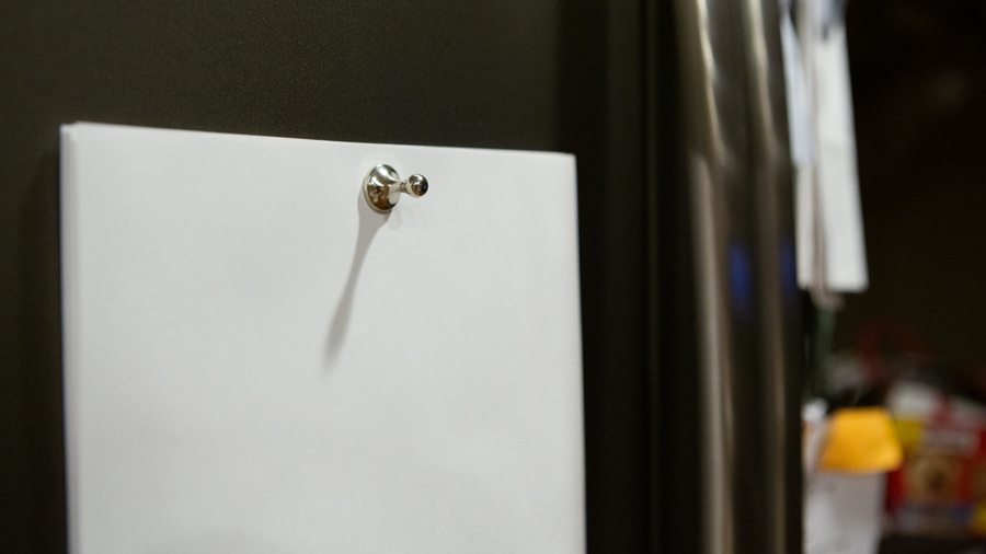
A single magnet can hold up to 15 sheets of paper!
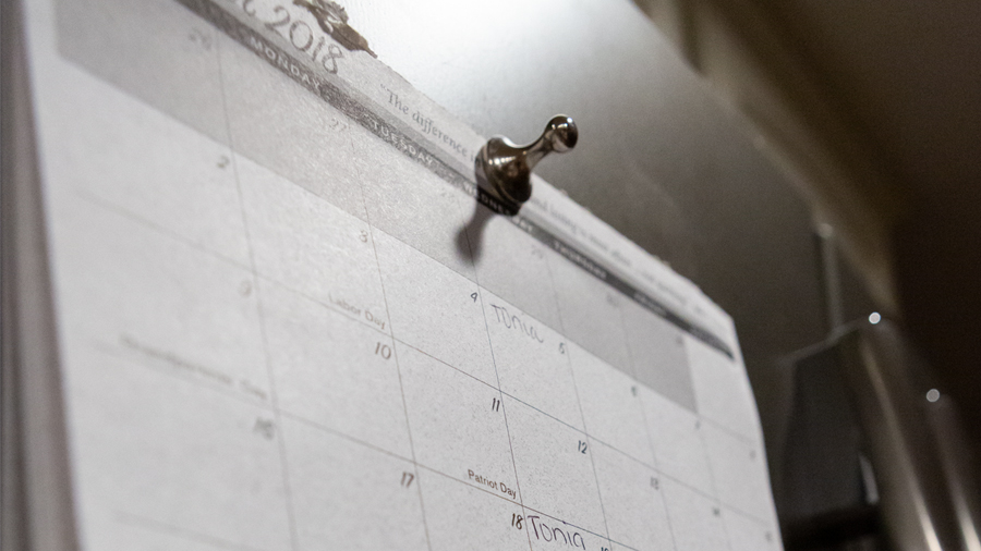
One magnet may also be able to hold an entire calendar to the front of a refrigerator.
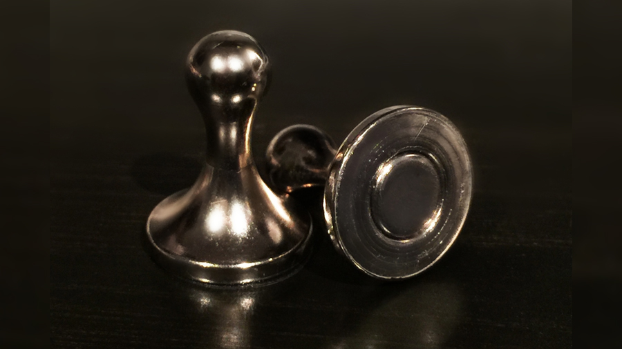
Prior to designing these, I scoured the review section of all of the other similar products to find out what people liked, and especially, what they didn’t like. I wanted to improve on the product and provide solutions to common issues. One of the primary complaints was that the metal shell of my competitors’ magnets scratched the surface of stainless steel refrigerators.
To combat this, I had my manufacturer add a small plastic film to the base of the magnet, similar to the material used in a phone screen protector. This kept a smooth layer between the magnet and the refrigerator door, preventing any scratches.
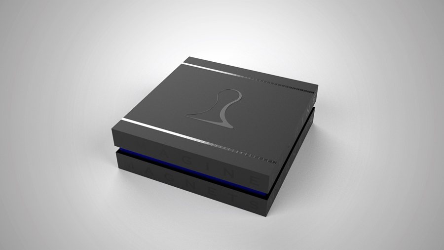
The next two pictures are models of my original packaging idea. I wanted a matte-black lid and base, with a glossy embossed brand logo, and two thin silver stripes above and below the logo. The brand name was also printed around the edges of the box using a UV gloss black.
The packaging ended up being too expensive due to the molds needed to manufacture the box. I settled for plastic zipper top bags for this first order, since I wanted to see how well they could sell first.
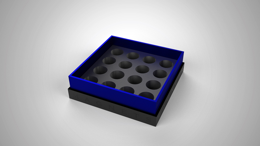
The inside of the box had a dense foam base, with an opening for each of the 16 magnets.
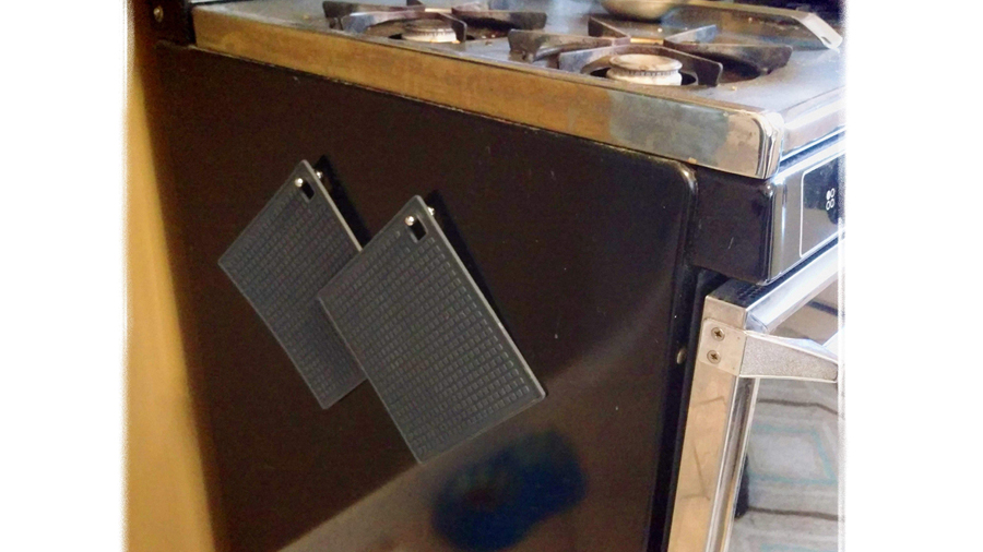
A customer sent me this picture showing how he decided to use his magnets. Not just for paper or photos, they can also be used for oven mitts, small kitchen utensils, or a set of keys. Two magnets will even hold a coffee mug!
Shameless plug: Etsy Page
Imagine Magnets is a brand I developed in 2018 for the purpose of selling on e-commerce sites, starting with Amazon.com. Most refrigerator magnets on Amazon were bulky, ugly, or not strong enough to hold anything up. I wanted to create something elegant that was strong enough to be used for more than just holding up a single picture.
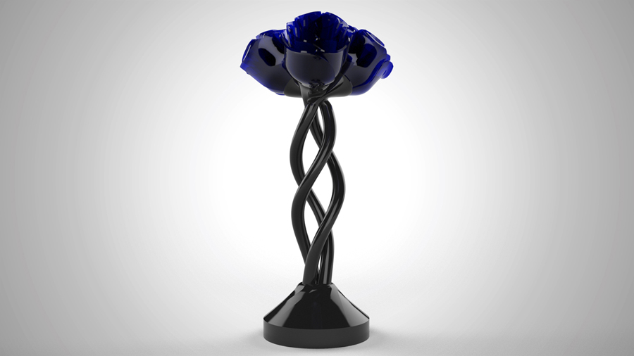
These flowers were designed and given as a gift. The three spiral posts are packed full of fiber optic strands and power wires for RGBW NeoPixel LEDs mounted in the base of the flowers. In the base, there is a Bluetooth chip, LiPo battery on a USB recharge circuit, and a panel of 64 RGB NeoPixel LEDs. Above the LED panel is a 3D printed grid of 64 holes into which bundles of fiber optic strands were glued. A customizable iPhone app was programmed to be able to control sequences and colors of the flowers and the fiber optics via Bluetooth.
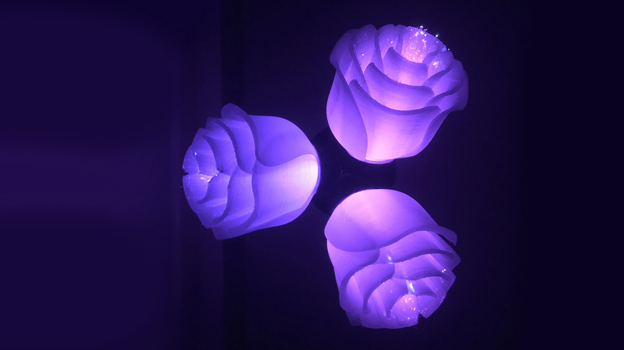
A single RGBW programmable LED sits at the base of each flower. The flower has concentric slots in the base that allow bundles of fiber optic strands to pass through.
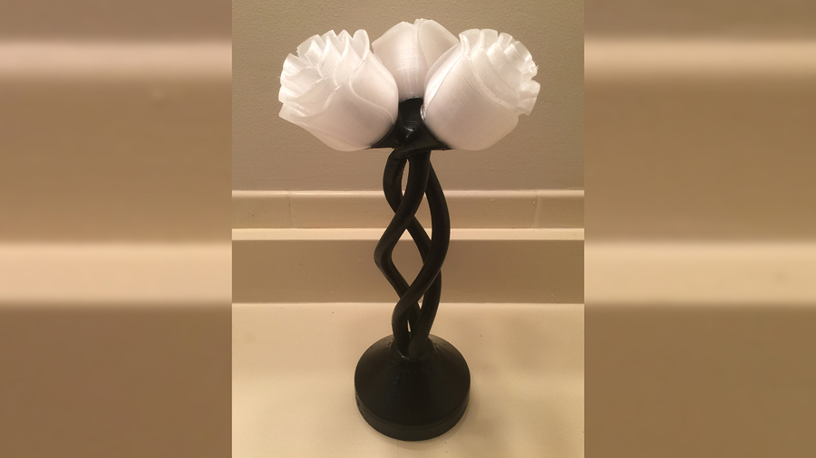
The base and spiral were painted to have the appearance of cast iron. Not seen in pictures, the base also has a ring of single 1.0mm fiber optic strands.
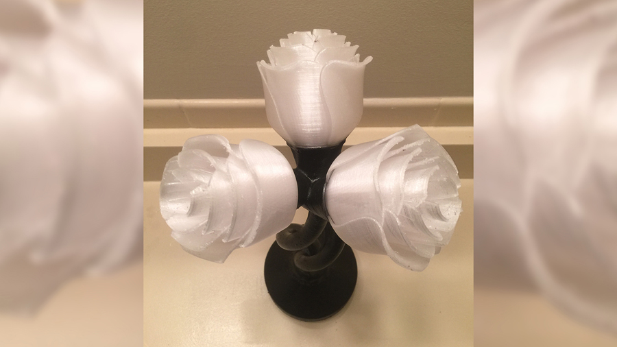
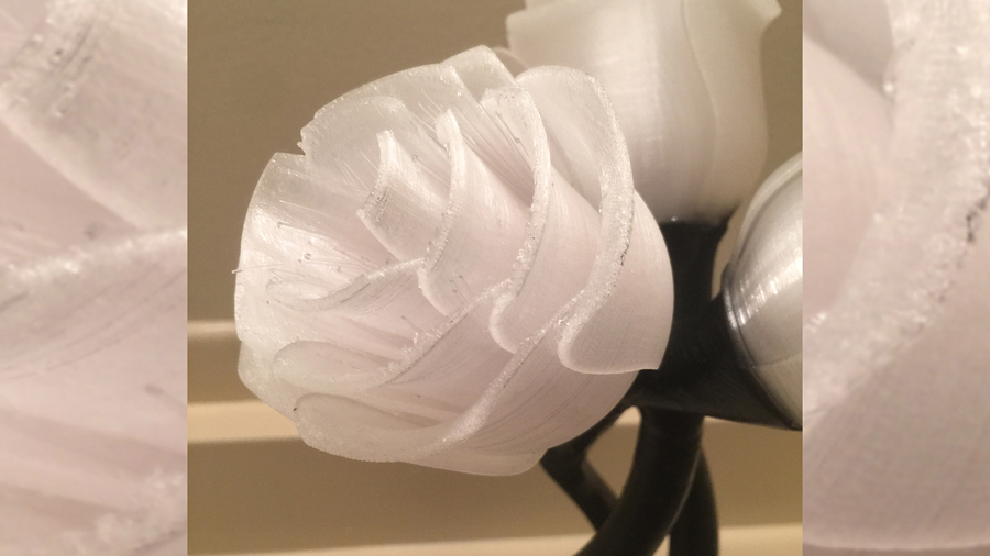
This video shows the programmed startup sequence of lighting effects. Once finished, the user can change the color of the fiber optic strands or individual flowers. Strobes, twinkles, and steady colors are possibilities.
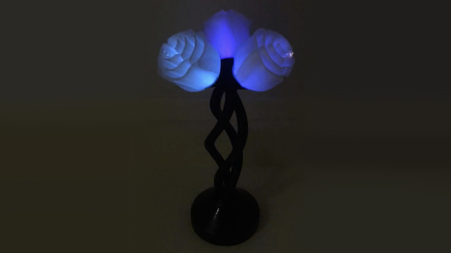
These flowers were designed and given as a gift. The three spiral posts are packed full of fiber optic strands and power wires for RGBW NeoPixel LEDs mounted in the base of the flowers. In the base, there is a Bluetooth chip, LiPo battery on a USB recharge circuit, and a panel of 64 RGB NeoPixel LEDs. Above the LED panel is a 3D printed grid of 64 holes into which bundles of fiber optic strands were glued. A customizable iPhone app was programmed to be able to control sequences and colors of the flowers and the fiber optics via Bluetooth.
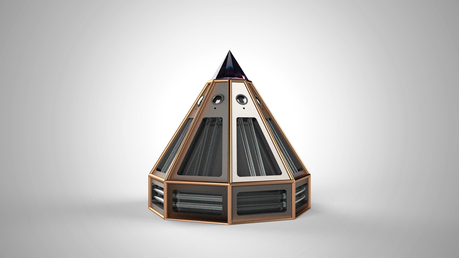
I started working with a touring magician to develop props for his show. Shown here is one of the props that was never fully developed, but I am proud of the design, nonetheless. The idea was that when an embarrassing question was asked to a child, this device would generate a series of alarms claiming the child was answering untruthfully.
The primary requirement in design was that the device could be seen from all points in the audience. With this shape, lights, sound and smoke effects would exit the device in all directions.
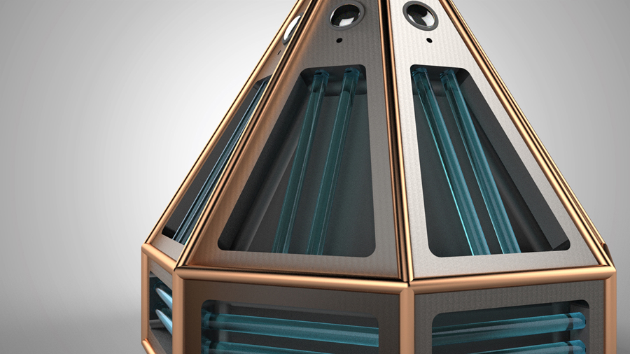
This device consisted of steel & copper 3D printing filament, clear acrylic rods, dozens of RGB LEDs, a mini fog machine, and a bottom-lit epoxy “diamond” gem on the top.
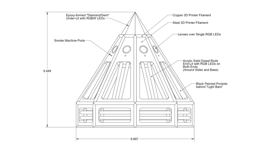
All of the primary features are shown here.
I started working with a touring magician to develop props for his show. Shown here is one of the props that was never fully developed, but I am proud of the design, nonetheless. The idea was that when an embarrassing question was asked to a child, this device would generate a series of alarms claiming the child was answering untruthfully.
The primary requirement in design was that the device could be seen from all points in the audience. With this shape, lights, sound and smoke effects would exit the device in all directions.
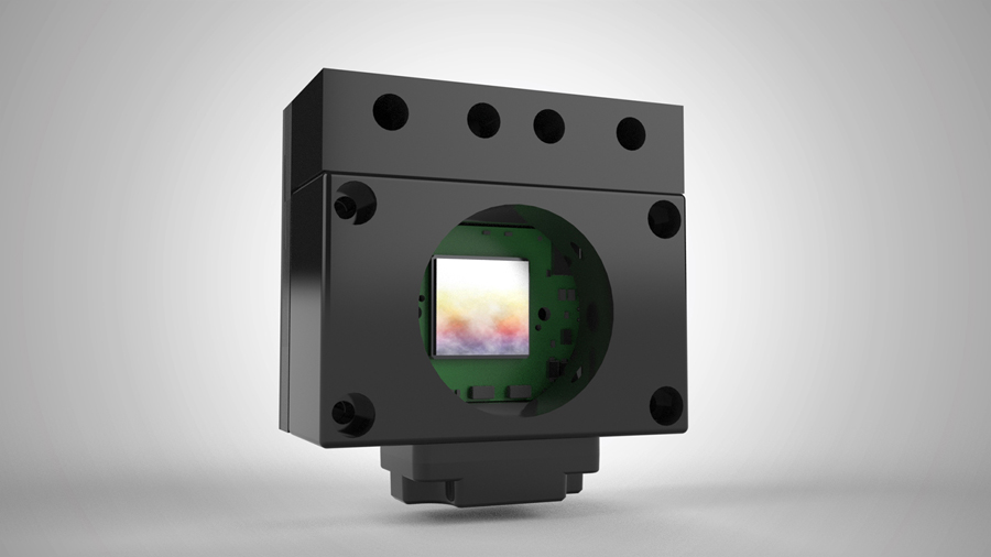
One of the industrial camera boards regularly purchased by the company for which I have been employed came inside of an enclosure produced by FLIR. The enclosure integrated seamlessly with our illumination and mounting systems. After using this camera/enclosure for many years, the enclosure was no longer available from the manufacturer. I developed this case to be 3D printed, allowing no disruption in production for the company.
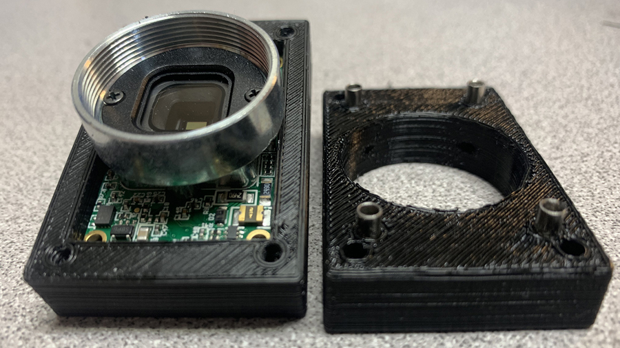
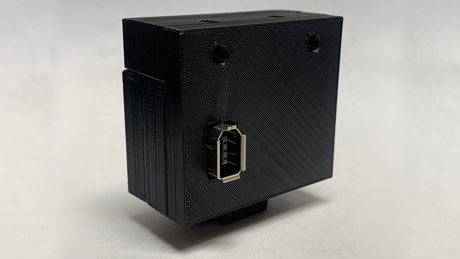
Shown here is the core camera board mounted in the rear enclosure. Steel spacers compressed into the front enclosure keep the board firmly in place.
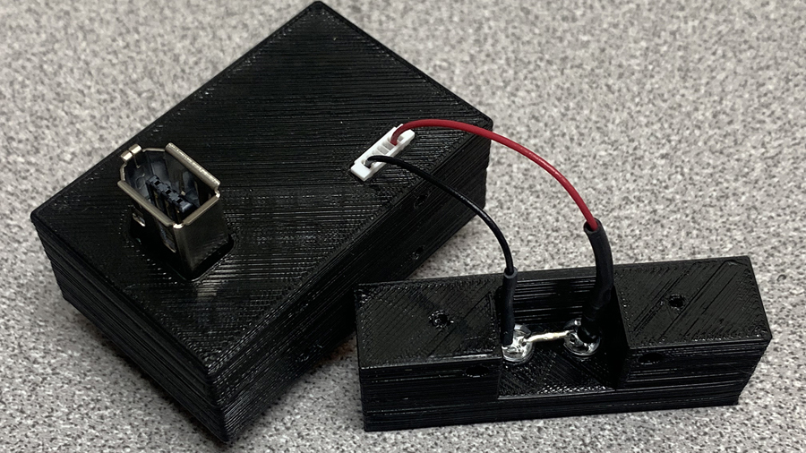
The rear enclosure has a precisely dimensioned opening for the camera board’s JST connector, which provides power to an external set of infrared LEDs. The material I used for the 3D printer can be directly tapped with 2-56 threads, and the LED mount is attached directly to the top of the camera enclosure.
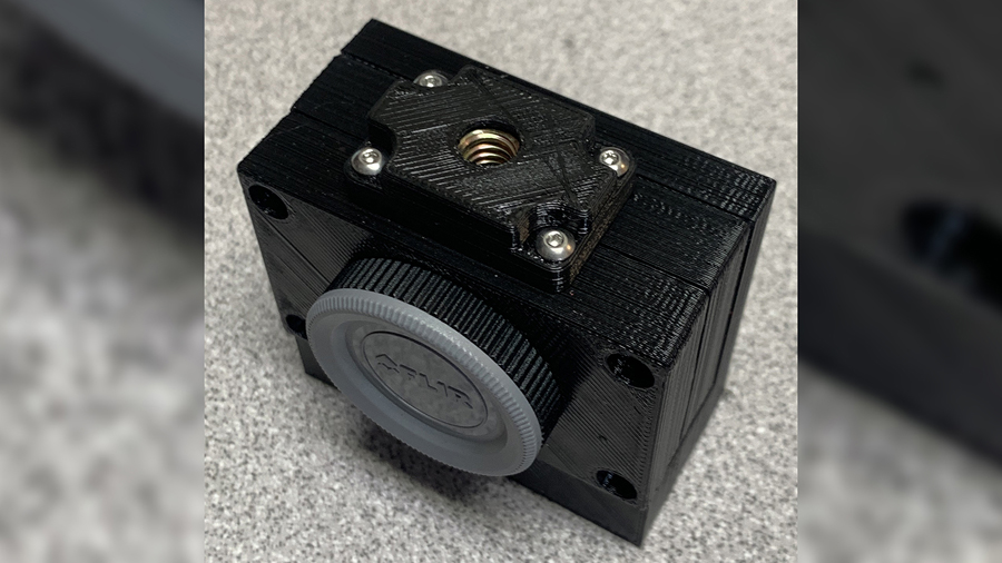
On the bottom of the camera enclosure, a tripod mount is attached, which consists of a 1/4-20 nut and a 3D printed nut enclosure.
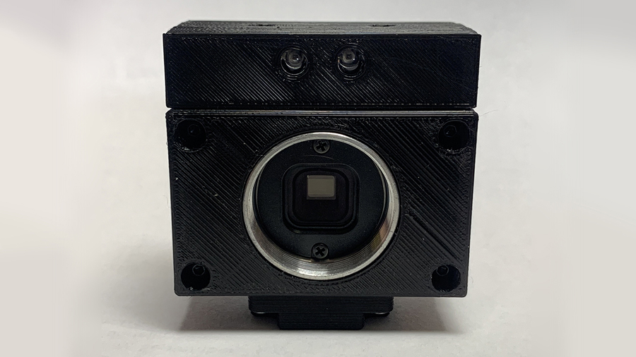
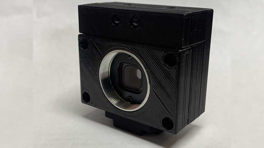
The CS style lens mount fits precisely flush with the front of the enclosure. The entire body remains relatively small with the addition of the top LEDs and the tripod mount.
[No text]
[No Text]
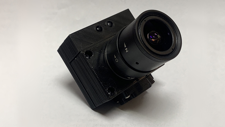
Camera body with varifocal lens.
One of the industrial camera boards regularly purchased by the company for which I have been employed came inside of an enclosure produced by FLIR. The enclosure integrated seamlessly with our illumination and mounting systems. After using this camera/enclosure for many years, the enclosure was no longer available from the manufacturer. I developed this case to be 3D printed, allowing no disruption in production for the company.
I was employed by a company that manufactured medical devices for balance disorder and vestibular system clinicians. One of the products was a set of goggles with cameras to track eye movement. Any time the software team needed to test updates to the code, it required pulling someone from the manufacturing floor to use as a test subject.
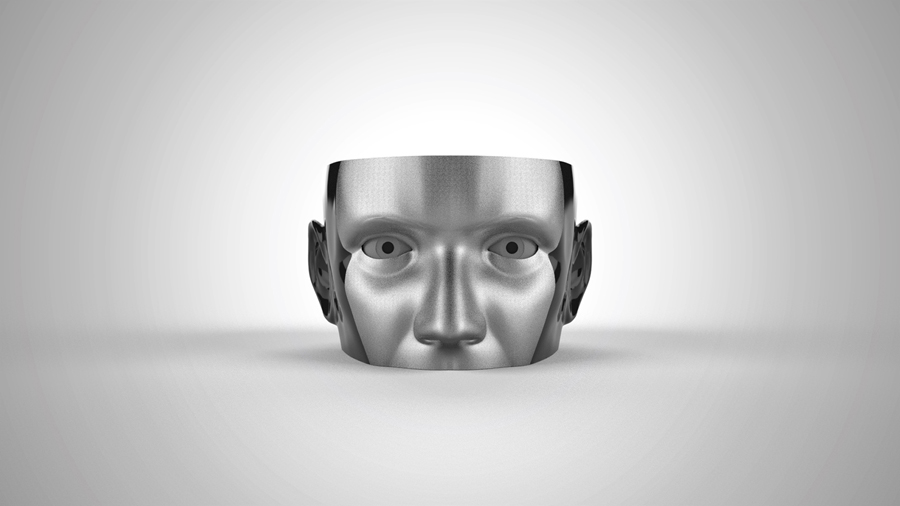
To keep production moving forward without the need to pull a body off the floor, I designed this testing fixture. It contains two eyes mounted to servo motors, with programmed motion sequences that closely match the software test conditions.
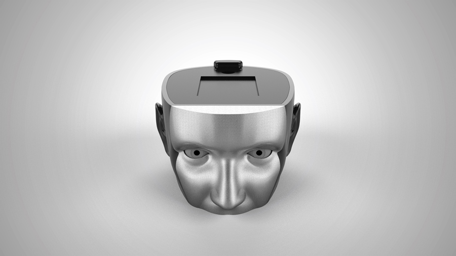
A push button at the rear of the lid activated one of three motion sequences. A single, double, or triple press of the button would begin an infinite loop of the desired sequence. An additional single press stopped the current sequence.
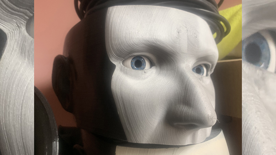
The eyeballs are hollow, with an open port representing the pupil. At the back of the eye is a layer of ultra-black, light-absorbing material. This absorbed the infrared illumination from the goggles - similar in function to a human pupil. For fun, I pulled out my paint set and painted irises on each of the three heads I built.
The fixture head was originally printed entirely in black filament, but the tracking software could not differentiate between the black in the pupil and the black in the face; the software was looking for a solid area of complete black. The silver filament resolved this issue.
The video shows each of the motion sequences, the illuminated push button in the head, and the internal components.
I have drawn out the mechanisms to to build a full-motion set of eyes for this fixture, including torsion, but I have not yet had the chance to build it.
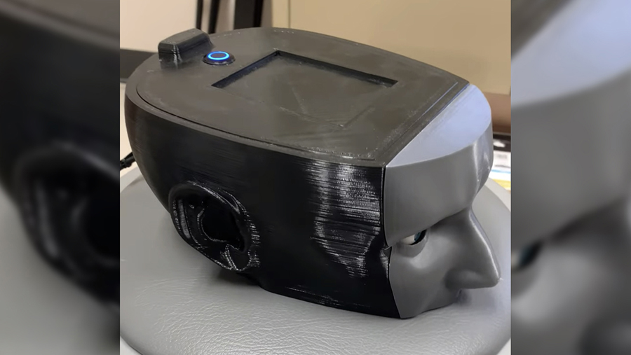
I was employed by a company that manufactured medical devices for balance disorder and vestibular system clinicians. One of the products was a set of goggles with cameras to track eye movement. Any time the software team needed to test updates to the code, it required pulling someone from the manufacturing floor to use as a test subject.
To keep production moving forward without the need to pull a body off the floor, I designed this testing fixture. It contains two eyes mounted to servo motors, with programmed motion sequences that closely match the software test conditions.

I held many roles with one of my employers, including Manufacturing Engineer, Sustaining Engineer, Product Design Engineer, and Biomedical Engineer. As Manufacturing engineer, I found ways to streamline production between departments. For one of our devices, once it completed final build in one room, it was moved to another room for final calibration. To avoid overflow in the calibration area, I designed this Kanban sensor system to notify the manufacturing floor when the calibration team was ready for another unit. Shown here is the wireless receiver.
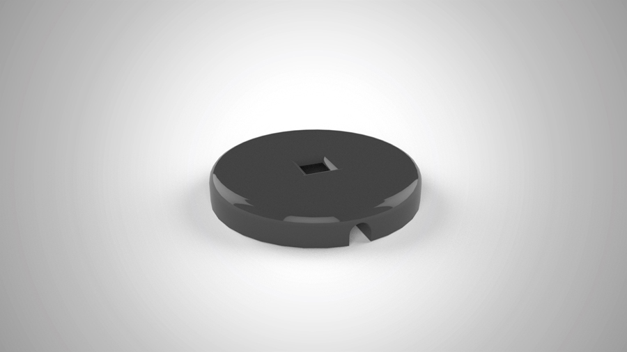
This is the shell of one of the proximity sensors located on the queue shelf. An array of these are placed where completed devices get set, and the proximity sensor sends a signal to a wireless transmitter.
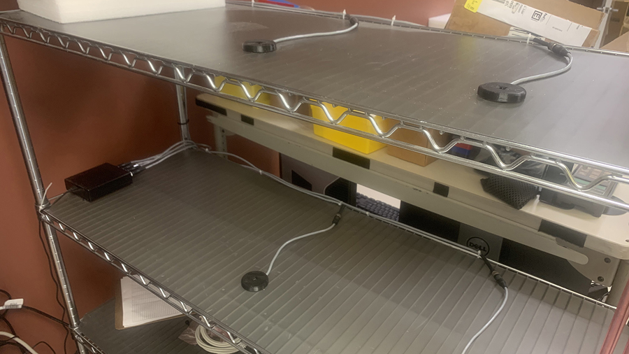
This is the array of sensors. To the left is the main “brain” to which the sensors are connected, and inside is a radio transmitter that sends values from 0-254 to the receiver.
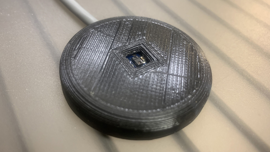
Within each proximity sensor is a tiny infrared LED and infrared sensor.
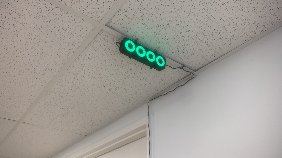
The wireless receiver is mounted on the ceiling on the manufacturing floor. Green tells the team that a space is open for an additional device. Red indicates the space is full.
This video shows how each sensor reacts to proximity and the corresponding color changes in the receiver.
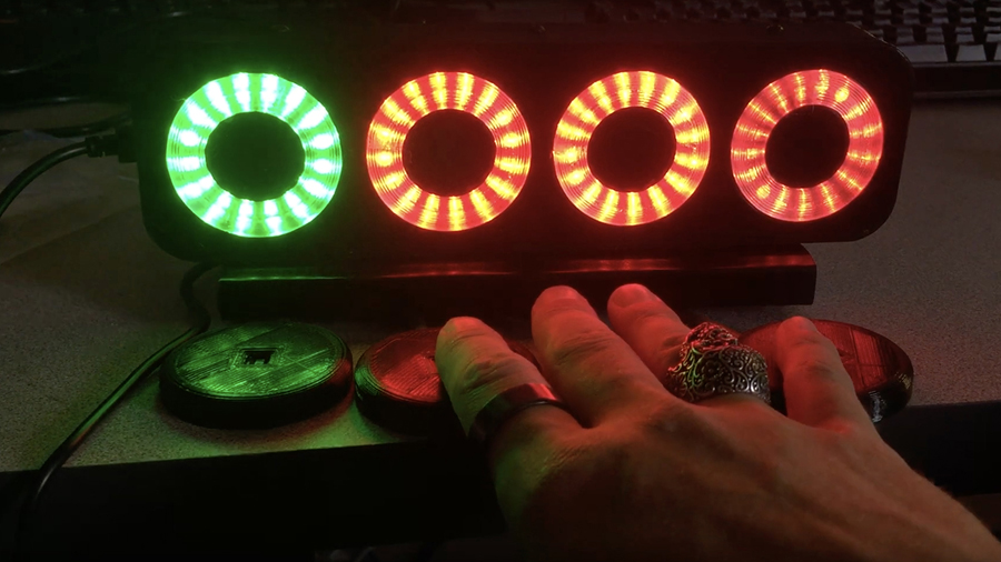
I held many roles with one of my employers, including Manufacturing Engineer, Sustaining Engineer, Product Design Engineer, and Biomedical Engineer. As Manufacturing engineer, I found ways to streamline production between departments. For one of our devices, once it completed final build in one room, it was moved to another room for final calibration. To avoid overflow in the calibration area, I designed this Kanban sensor system to notify the manufacturing floor when the calibration team was ready for another unit. Shown here is the wireless receiver.
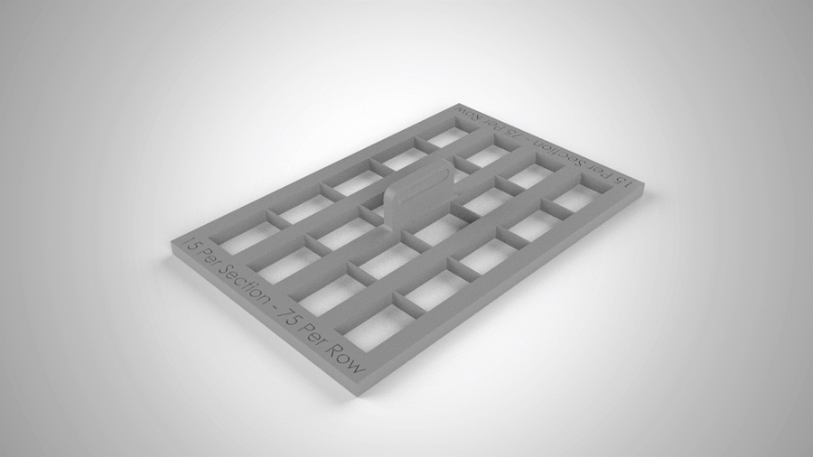
I designed a fixture to guarantee precise quantities of small parts in packaging. One of the complaints from our parent company was that a box of 300 parts didn’t always come out to exactly 300. This fixture, when placed over the foam tray within the box, guaranteed an exact count of 300 units.
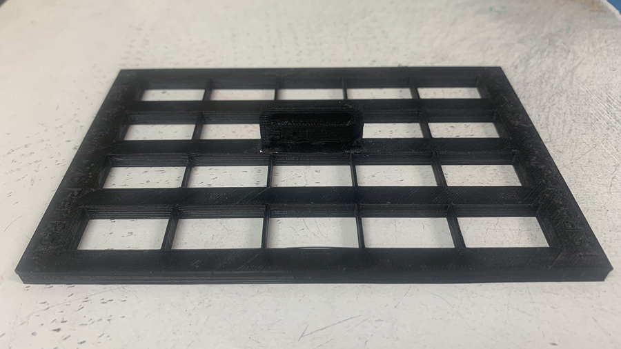
Here is the 3D printed fixture
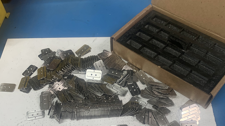
300 of these small parts needed to be quickly and efficiently placed in the foam tray.
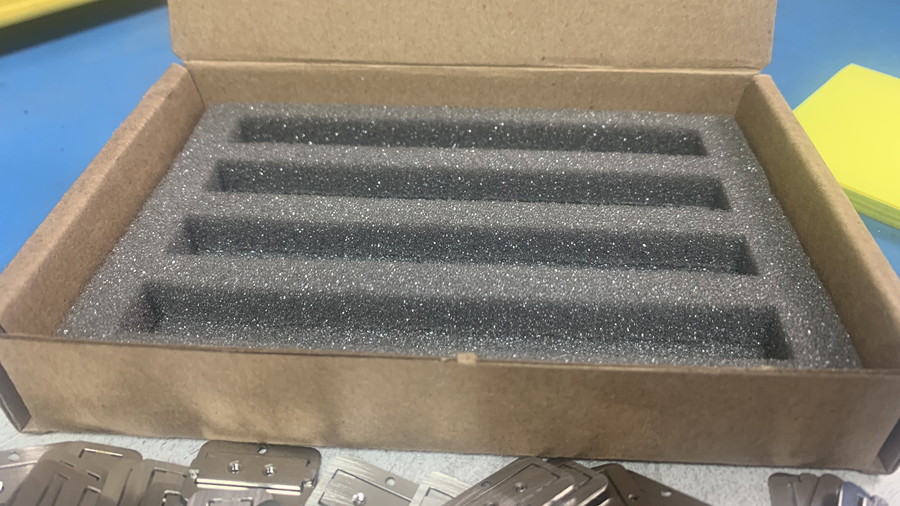
[No Text]
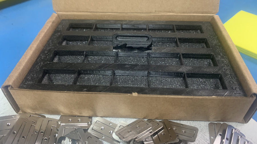
Each opening allows for no more than 15 units
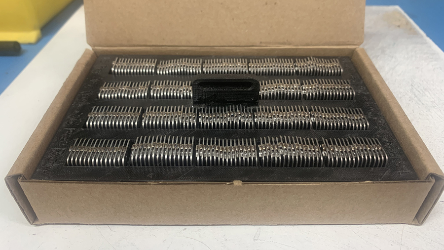
Once the fixture is fully loaded, it is lifted off the foam to allow the parts to settle into place.
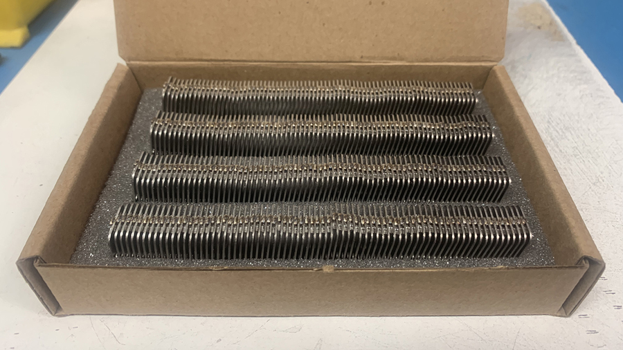
These parts are then sent to the end user, precisely 300 pieces guaranteed.
I designed a fixture to guarantee precise quantities of small parts in packaging. One of the complaints from our parent company was that a box of 300 parts didn’t always come out to exactly 300. This fixture, when placed over the foam tray within the box, guaranteed an exact count of 300 units.
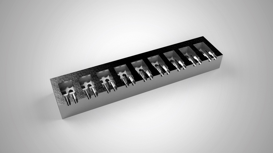
While passing through the manufacturing floor one day, I noticed a few of our hand made cable assemblies being completed one at a time. In my head, I imagined an entire array of cables laid out on the table so each step could be applied to multiple cables at once. Shown here is a fixture that holds the ends of up to nine firewire cable pairs. Using this fixture attached to the end of a table, small sections of heat shrink that paired the cables together could be applied to many cables at one time, without the risk of overheating a single cable pair.
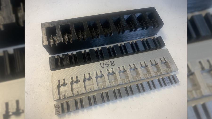
These are fixtures I made for both Firewire and USB cables sets. The additional channel blocks are used to guide and keep the cable pairs together further down the preparation surface.
While passing through the manufacturing floor one day, I noticed a few of our hand made cable assemblies being completed one at a time. In my head, I imagined an entire array of cables laid out on the table so each step could be applied to multiple cables at once. Shown here is a fixture that holds the ends of up to nine firewire cable pairs. Using this fixture attached to the end of a table, small sections of heat shrink that paired the cables together could be applied to many cables at one time, without the risk of overheating a single cable pair.
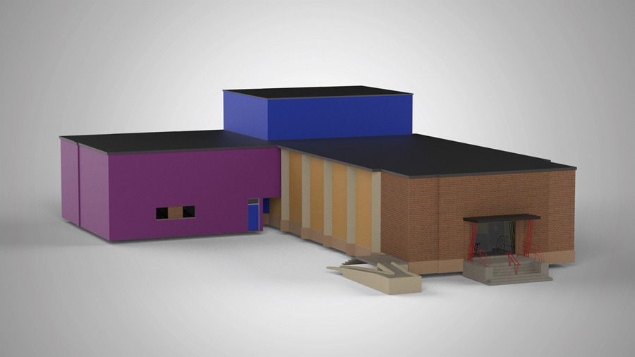
I have done a lot of work for the Legacy Theatre in Springfield, IL. The theatre was looking to add to or upgrade the security, WifFi, and audio systems throughout the building. Everything was to be connected via Cat6 cabling. To better communicate the needs of the project to contractors for cabling, WiFi node, and CCTV camera locations, I created an inch-accurate model of the facility in Solidworks. The next two pictures show the actual building.
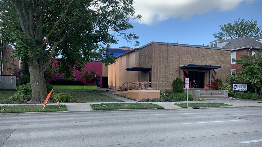
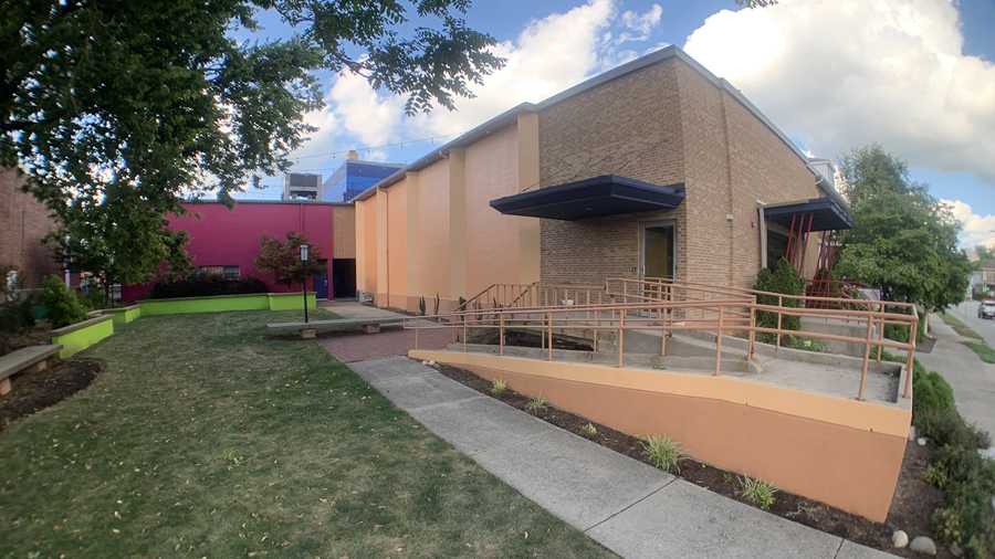
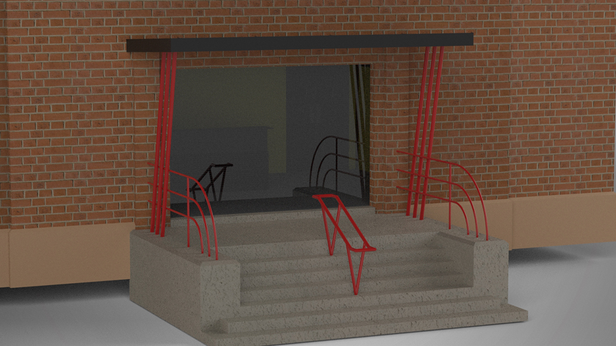
Referencing the following photo, sans doorway, I attempted to produce a model with as much attention to detail as I could. Though not seen in the second image, the entire lobby has also been recreated.
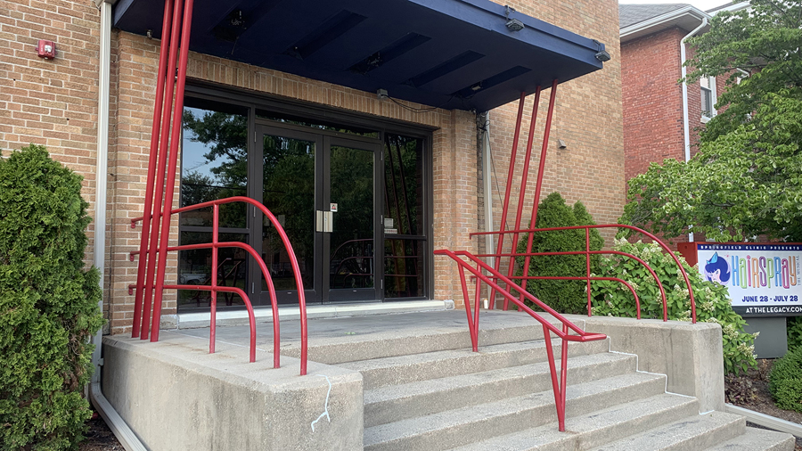
The railing in the CAD model is accurate to the quarter inch.
I have done a lot of work for the Legacy Theatre in Springfield, IL. The theatre was looking to add to or upgrade the security, WifFi, and audio systems throughout the building. Everything was to be connected via Cat6 cabling. To better communicate the needs of the project to contractors for cabling, WiFi node, and CCTV camera locations, I created an inch-accurate model of the facility in Solidworks. The next two pictures show the actual building.
Tool is one of my favorite bands. Some very good friends of mine formed a Tool tribute band. I recorded them.
The following videos are samples of my project. I recorded the video with a DSLR roving camera and an assortment of GoPro cameras throughout the room, including mounted to the head stocks of the guitars. I also multitracked 32 channels of audio from the soundboard into my recording software, and mixed it down to sound as close to the original album as possible, given the equipment, room, and microphone selection.
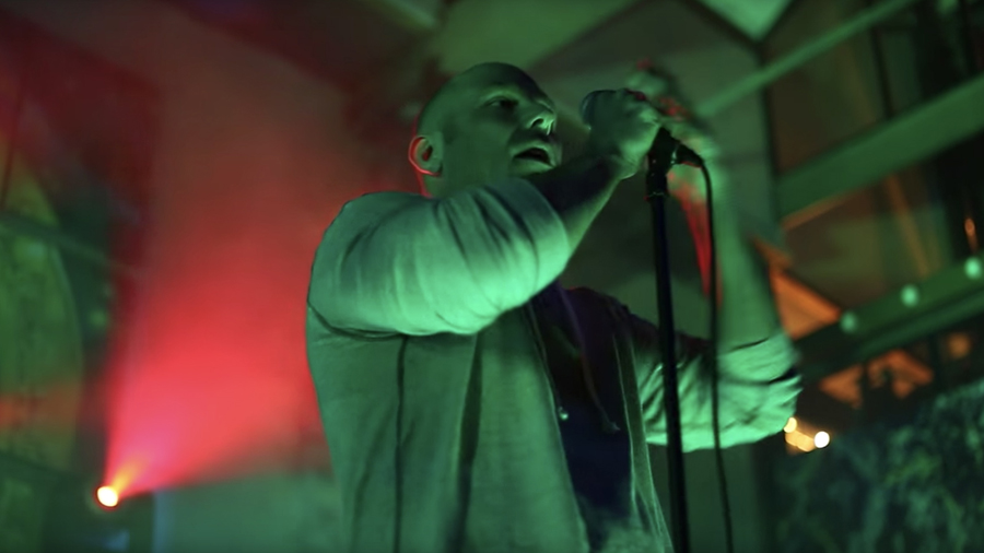
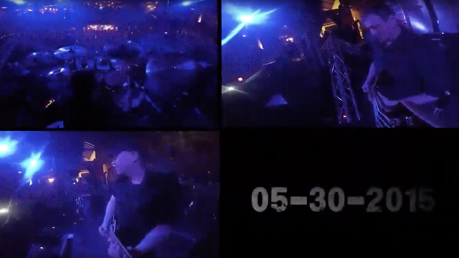
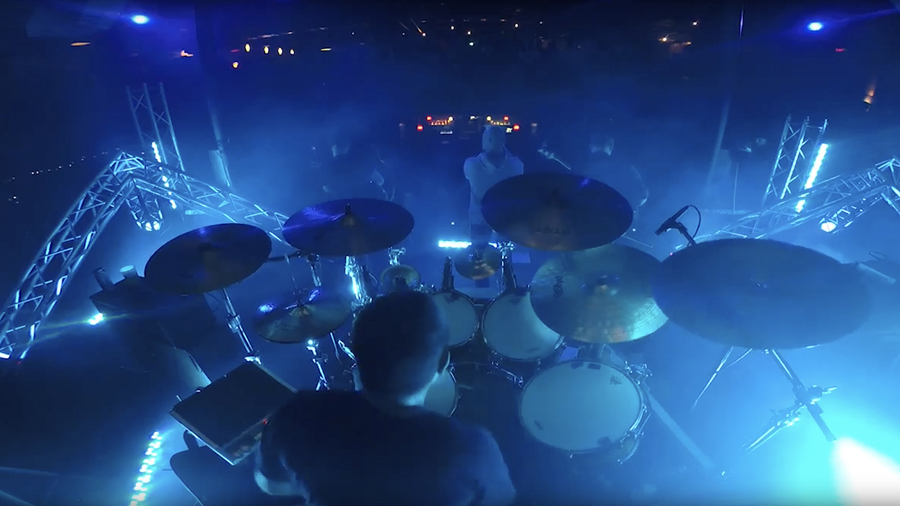
Tool is one of my favorite bands. Some very good friends of mine formed a Tool tribute band. I recorded them.
The following videos are samples of my project. I recorded the video with a DSLR roving camera and an assortment of GoPro cameras throughout the room, including mounted to the head stocks of the guitars. I also multitracked 32 channels of audio from the soundboard into my recording software, and mixed it down to sound as close to the original album as possible, given the equipment, room, and microphone selection.
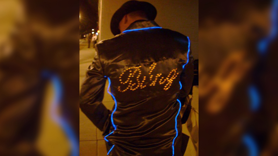
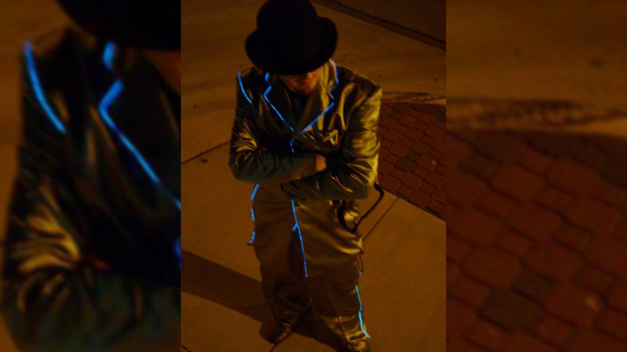
This was in 2001, long before electroluminescent wire showed up on America’s Got Talent. The story of how we got here follows on the next slides.
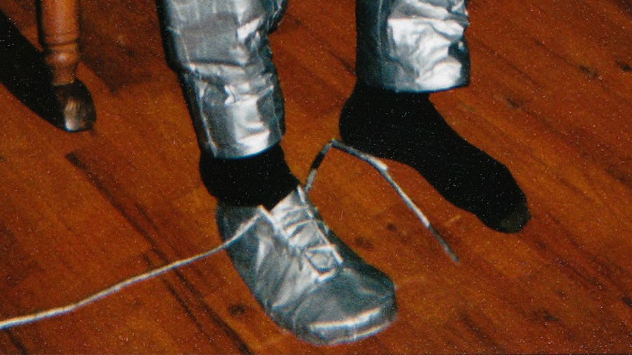
Sometime around 1997, I was making everything out of duct tape. Infact, my best friend, Geoff, and I became President and Vice President of an Illinois Chapter of some kind of duct tape club of which I DO NOT remember the name. While everyone was making duct tape wallets, I had bigger dreams. I started with duct tape shoes.
The only thing that wasn’t duct tape was the soles. I cut out cardboard in the shape of my feet, and built tape up from there. Even the shoelaces consisted of a single, very long, strip of duct tape rolled up to form a shoelace.
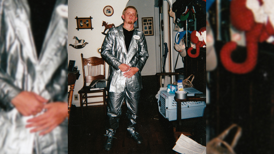
Since I am always trying to outdo myself, I needed to make more than the duct tape shoes. So I made I duct tape suit. Now, most folks would take an existing suit and wrap it with tape. Not me. I bought a zoot suit fabric plan, and then I created panels of sticky-side to sticky-side tape, cut them out according to the suit plan, and taped them together to form the masterpiece you see here.
The oval-shaped paper on the lapel reads, “Boot-in-Ear.”
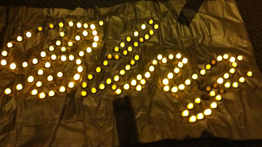
My senior prom was coming up. Everyone knew about my duct tape suit, and they asked if that would be used for prom. Since I once again had to outdo myself, I needed something bigger. Thus, the electroluminescent wire, shiny silver suit was born. Not only were the edges of the suit lines with blue and aqua EL wire, I sewed into the back of the suit, under the fabric, 150 LEDs that spelled out “Bling” in cursive. These LEDs were wired to a button in my belt that could be activated on cue. To top it off, I mounted a battery-powered black light into my top hat and sprayed fluorescent hair spray into my hair for that extra special touch.
Yes, this path has created many great memories for myself and my friends. But please don’t repeat this story - it’s just between you and me.
This was in 2001, long before electroluminescent wire showed up on America’s Got Talent. The story of how we got here follows on the next slides.